
Slicing method and method for manufacturing epitaxial wafer

a technology of epitaxial wafers and slicing methods, which is applied in the direction of saw chains, sawing devices, and under protective fluids, etc., can solve the problems of irregular direction of the blade, and achieve excellent reproducibility, improved work efficiency, and easy slicing.

Active Publication Date: 2012-07-03
SHIN-ETSU HANDOTAI CO LTD
View PDF10 Cites 1 Cited by
  • Summary
  • Abstract
  • Description
  • Claims
  • Application Information

AI Technical Summary

Benefits of technology

[0020]Therefore, in view of the above-explained problem, it is an object of the present invention to provide a slicing method that can easily perform slicing with excellent reproducibility with Sori of all wafers being trued up to one direction when slicing an ingot by using a wire saw. Additionally, another object is providing an epitaxial wafer manufacturing method that does not require Bow measurement and a reversing operation of sliced wafers sliced out like a conventional example.
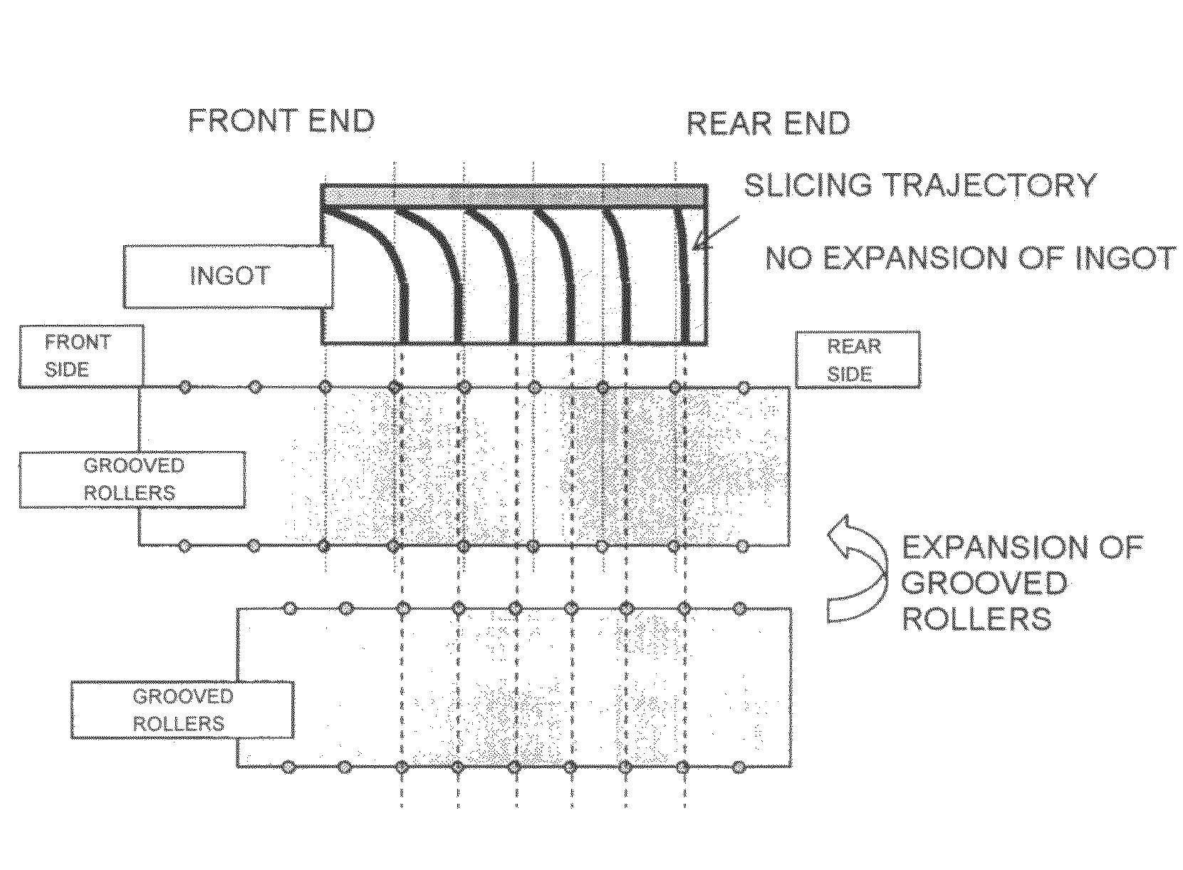
[0024]Since the supply temperature profile of the slurry for slicing is set based on the above relationship inherent to each wire saw and the slurry for slicing is actually supplied to perform slicing, Sori of all the wafers to be sliced out can be easily uniformed in one direction with excellent reproducibility. Furthermore, since Sori of all the wafers can be uniformed in one direction, it is possible to eliminate an operation of measuring a shape of each wafer in advance and turning over each wafer to align directions of Bows so that epitaxial growth can be performed on a desired surface side before depositing an epitaxial layer as will be explained later.
[0029]As explained above, Sori of all wafers to be sliced out can be further readily uniformed in one direction based on whether the supply temperature profile of the slurry for slicing is set at least as the profile that the supply temperature is gradually increased when the slicing depth of the ingot reaches ½ of the diameter or whether the supply temperature profile of the slurry for slicing is set as the profile that the supply temperature is gradually increased after start of slicing the ingot.
[0031]A explained above, if wafers having Sori aligned in one direction are sliced out based on the slicing method and the epitaxial layer is deposited on each wafer having the Sori aligned in one direction, it is possible to eliminate a conventionally required operation of measuring directions of Bows of wafers sliced out from an ingot in advance before performing epitaxial growth and turning over each wafer to align directions of Bows to one direction when the directions are not aligned, thereby greatly a work efficiency can be improved.
[0032]According to the slicing method of the present invention, slicing can be easily performed with excellent reproducibility while uniforming Sori of all wafers in one direction. Furthermore, since all wafers can be sliced out with Sori thereof while being aligned in one direction, the operation of measuring Bows and turning over the wafers sliced out from the ingot does not have to be performed, thus a work efficiency can be considerably improved.

Problems solved by technology

However, when an ingot is sliced out based on a conventional method, Bow directions usually become irregular at respective positions of the ingot in an axial direction.
Therefore, when all of the wafers obtained by slicing are measured in a process before polishing and they have Bows in a direction opposite to a desired direction, the wafers must be turned upside down one by one to be put into, e.g., a polishing apparatus in a reversed direction, which is troublesome.

Method used


Image

  • Slicing method and method for manufacturing epitaxial wafer
  • Slicing method and method for manufacturing epitaxial wafer
  • Slicing method and method for manufacturing epitaxial wafer

Examples


example

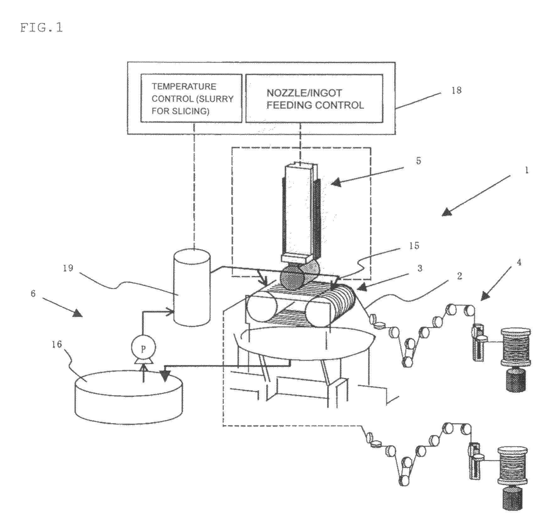
[0097]The slicing method according to the present invention was carried out by using the wire saw depicted in FIG. 1. As a preliminary test, the same silicon ingot as a silicon ingot having a diameter of 300 mm and an axial length of 180 mm to be used in a main-slicing process was sliced into wafers while supplying a slurry for slicing and controlling a supply temperature thereof.

[0098]It is to be noted that a wire having a width of 160 μm was used, and a tensile force of 2.5 kgf was applied to cause the wire to travel in a reciprocating direction at an average speed of 500 m / min in a cycle of 60 s / c, thereby performing slicing. It is to be noted that a material obtained by mixing GC#1500 with a coolant at a weight rate of 1:1 was used as a slurry. These conditions are the same as slicing conditions in a main-slicing process that is carried out later.

[0099]Further, at this time, a supply temperature of a slurry for slicing was increased from 22° C. to 35° C., and expansion of a groo...


PUM

PropertyMeasurementUnit
temperatureaaaaaaaaaa

Abstract

A wafer slicing method includes winding a wire around rollers and pressing the wire against an ingot while supplying slurry to the rollers. A previously conducted experiment provides a supply temperature profile of the slurry during the slicing process and the relationship to the axial displacement of the rollers. This relationship is used to implement slurry delivery during the slicing process. The resultant wafers are bowed in a uniform direction. This slicing method provides excellent reproducibility in addition to producing wafers that are bowed in a uniform direction.

Description

TECHNICAL FIELD[0001]The present invention relates to a slicing method for slicing, e.g., a silicon ingot or an ingot of a compound semiconductor into many wafers by using a wire saw and a method for manufacturing an epitaxial wafer by depositing an epitaxial layer on a wafer sliced out based on the slicing method.BACKGROUND ART[0002]In recent years, an increase in size of a wafer is demanded, and a wire saw is mainly used to slice an ingot with this increase in size.[0003]The wire saw is a apparatus that allows a wire (a high-tensile steel wire) to travel at a high speed and presses an ingot (a work) against the wire to be sliced while applying a slurry to the wire, thereby slicing the ingot into many wafers at the same time (see Japanese Unexamined Patent Publication (Kokai) No. 262826-1997).[0004]Here, FIG. 11 shows an outline of an example of a general wire saw.[0005]As shown in FIG. 11, a wire saw 101 mainly includes a wire 102 that slices an ingot, grooved rollers 103 (wire gu...

Claims


Application Information

Patent Timeline
Patent Type & Authority Patents(United States)
IPC IPC(8): B24B53/095
CPCB24B27/0633B28D5/0064B28D5/045B28D5/007Y10T117/1004Y10T117/10Y10T83/9292Y10T83/0443H01L21/30B24B27/06B28D5/04
Inventor OISHI, HIROSHINAKAMATA, DAISUKE
Owner SHIN-ETSU HANDOTAI CO LTD
Learn More