Self-Moving Device and Control Method Thereof

a self-moving, lawnmower technology, applied in the direction of distance measurement, instruments, using reradiation, etc., can solve the problems of easy strength breakage, affecting climbing and obstacle surmounting, and easy run-over damage to obstacles, etc., to achieve continuous and normal operation of the track wheel

Active Publication Date: 2019-06-06
POSITEC POWER TOOLS (SUZHOU) CO LTD
View PDF0 Cites 8 Cited by
  • Summary
  • Abstract
  • Description
  • Claims
  • Application Information

AI Technical Summary

Benefits of technology

[0116]By using the track wheel and track-type travel mechanism, when mud or grass enters an engagement portion between the track and the track wheel, the mud or grass may enter the engagement slot and be discharged, via the through hole, to the second sides of the flanges, thereby preventing the track wheel from carrying mud or grass and ensuring continuous and normal operation of the track wheel. The embodiments of the present invention further disclose a track travel mechanism including the track wheel and a track-type robotic lawn-mower.

Problems solved by technology

However, the design affects the climbing and obstacle surmounting performance of the track-type robotic lawn-mower.
More importantly, the track has a good obstacle surmounting capability and does not stop moving immediately when colliding with an obstacle (including a human body), and therefore the further movement of the track lawn-mower may, on one hand, cause run-over damage to the obstacle, and on the other hand, enable a cutting component (for example, a blade) to be directly in contact with the obstacle and cause a damage.
In the travel process of the track-type robotic lawn-mower, the track may generate a tension, the tension may generate a straining force on a bracket where a driving wheel and a guide wheel are connected to the housing, and therefore a strength break may be easily caused at the bracket where the wheel set is connected to the housing.
The straining force may cause a deformation in the housing and a wheel shaft, and therefore the track may be easily disengaged from the driving wheel and the guide wheel.

Method used


Image

  • Self-Moving Device and Control Method Thereof
  • Self-Moving Device and Control Method Thereof
  • Self-Moving Device and Control Method Thereof

Examples


Embodiment Construction

[0131]The detailed description and technical content related to the present invention are described below with reference to the accompanying drawings. However, the accompanying drawings appended only provide reference and description, but are not intended to limit the present invention.

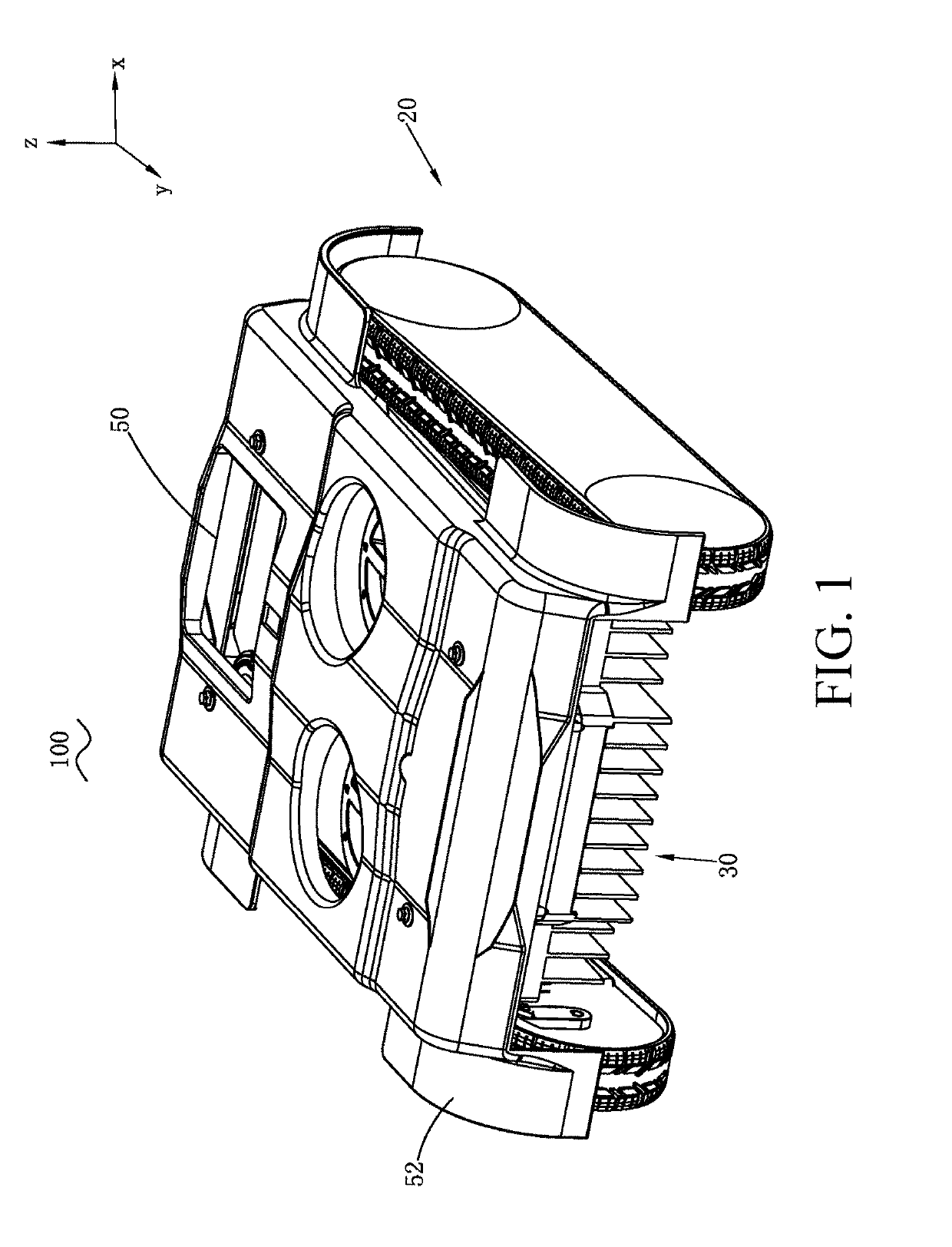
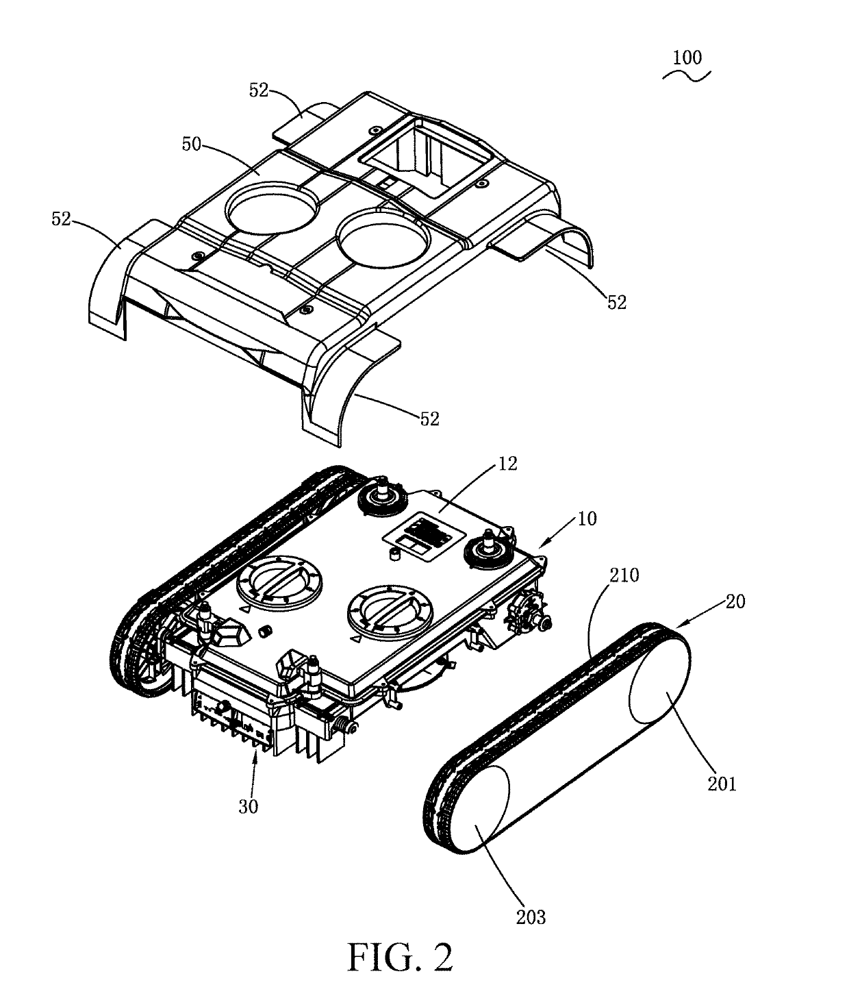
[0132]As shown in FIG. 1 and FIG. 2, the embodiments of the present invention provide a self-moving device. The self-moving device may be specifically a device capable of moving autonomously such as a robotic lawn-mower, an autonomous snow sweeper, or a robotic sweeper. This embodiment provides a robotic lawn-mower 100. The robotic lawn-mower 100 includes a housing 10, travel modules 20 located on two sides of the housing 10, a working module 108 located at a bottom part of the housing 10, an electric motor 102 located in the housing 10, a control module 104 configured to control the robotic lawn-mower 100 to work and travel autonomously, and an energy module 106 configured to provide energies.

[0133]I...


PUM


Abstract

A self-moving device, including: a housing, provided with a motor; a moving module, including a track, the track, driven by the motor, moving the self-moving device; a working module; a control module, configured to control movement of the moving module and working of the working module; and a first sensor and a second sensor, configured to detect an obstacle in a moving direction of the self-moving device. The first sensor is configured to detect a first area in the moving direction, the second sensor is configured to detect a second area in the moving direction, and the first area and the second area are arranged perpendicular to the moving direction. The control module controls a moving manner of the self-moving device according to sensing results of the first sensor and the second sensor.

Description

TECHNICAL FIELD[0001]The present invention relates to a self-moving device, and in particular, to a track-type robotic lawn-mower.Related Art[0002]With continuous advancement in computer technologies and artificial intelligent technologies, robotic lawn-mowers similar to robotic self-moving devices have already gradually entered people's lives. A robotic lawn-mower can autonomously mow and get charged in a user's lawn without intervention of a user. By using such an autonomous working system, no efforts are needed for management after the system is set once, and users are released from household works, such as cleaning and lawn maintenance, which are boring, time consuming, and labor intensive.[0003]A conventional robotic lawn-mower usually uses a wheel-type travel mechanism. However, the wheel-type travel mechanism is poor in performance such as climbing and obstacle surmounting and cannot adapt to a complex terrain. With respect to the problems in the wheel-type travel mechanism, ...

Claims


Application Information

Patent Timeline
Patent Type & Authority Applications(United States)
IPC IPC(8): G05D1/02B62D55/06B62D25/16A01D34/00G01S15/93G01C3/08G01D5/14G01D5/20G01S15/931
CPCG05D1/0214B62D55/06B62D25/16G05D1/0259G05D1/0255A01D34/008G01S15/931G01C3/08G01D5/142G01D5/20G05D2201/0208A01D2101/00A01D69/02A01D34/00A01D67/00B62D55/065B62D55/08G01S17/931
Inventor CESTONARO, ANDREAANDRIOLO, PAOLOGAO, ZHENDONGJIAO, SHIPINGDU, JIANGRAN, YUANZHONGTANG, XIURUI
Owner POSITEC POWER TOOLS (SUZHOU) CO LTD
Why Eureka
Try Eureka