Arithmetic unit

a technology of arithmetic units and units, applied in the field of arithmetic units, can solve the problems of increasing the number of software products in the ecu, and achieve the effect of reducing the number of software parts

Active Publication Date: 2019-06-06
YAZAKI CORP
View PDF6 Cites 0 Cited by
  • Summary
  • Abstract
  • Description
  • Claims
  • Application Information

AI Technical Summary

Benefits of technology

[0012]According to the above-described mode, since it is unnecessary to prepare an arithmetic unit for each input processing logic, the software part number can be reduced.

Problems solved by technology

For this reason, there posed a problem that a software product number of the ECU increases.

Method used


Image

  • Arithmetic unit
  • Arithmetic unit
  • Arithmetic unit

Examples


Embodiment Construction

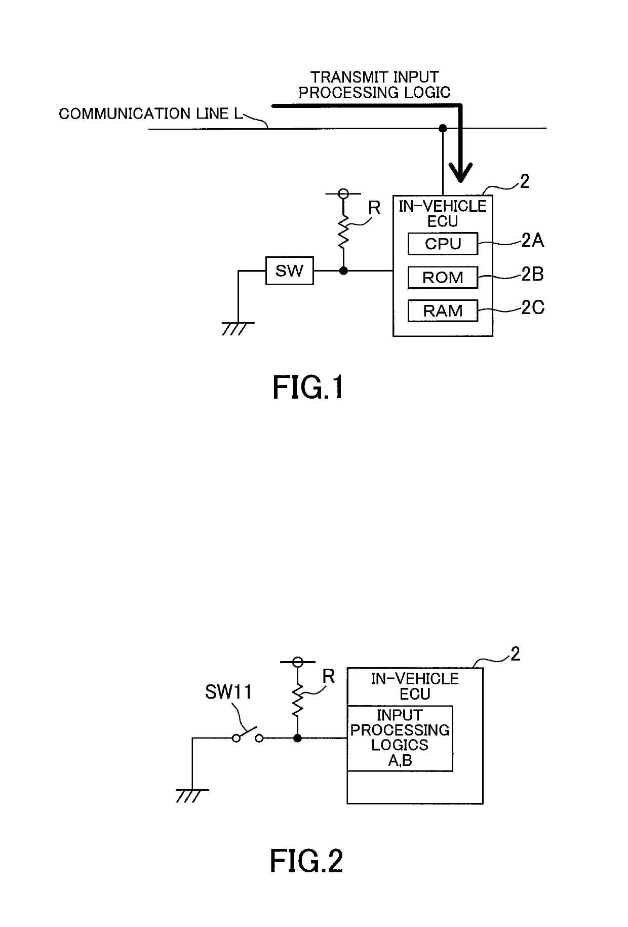
[0020]Hereinafter, an embodiment of the present invention will be described with reference to FIG. 1. FIG. 1 is a block diagram showing an embodiment of an in-vehicle system incorporating an in-vehicle ECU as an arithmetic device of the present invention. The in-vehicle system 1 includes switch SW and load (not shown) arranged at various locations of the vehicle body and a plurality of in-vehicle ECUs 2 connected to the switch SW and the load.

[0021]The switch SW is connected in series with the resistor R between a power supply and ground. A voltage at a connection point of a resistor R and a switch SW is input to the in-vehicle ECU 2.

[0022]A plurality of in-vehicle ECUs 2 is arranged at various locations of the vehicle body and is communicably connected to each other via a communication line L. The in-vehicle ECU 2 has a CPU 2A, a well-known microcomputer including ROM 2B and a RAM 2C. The CPU 2A performs various processing and controls for predetermined program. The ROM 2B is a rea...


PUM


Abstract

Provided is an arithmetic processing to reduce a number of parts as it is not necessary to prepare an operation device for each input processing logic. A plurality of types of input processing logics is stored in the ROM, and CPU selects one of the plurality of types of input processing logics and executes input processing according to the selected input processing logic. As a result, there is no need to prepare the ECU for each input processing logic, reducing the number of parts.

Description

TECHNICAL FIELD[0001]The present invention relates to an arithmetic unit.BACKGROUND ART[0002]For example, in a vehicle, various loads such as a lamp, an electric motor, and a heater, and switches for manipulating these loads are arranged in a state where they are distributed at various places of the vehicle body. Therefore, it has been conceived that a plurality of ECUs (arithmetic devices) that can communicate with each other is arranged at various places of the vehicle body, and these ECUs control loads or switches (see Patent Documents 1 and 2).[0003]The above-mentioned ECU differs depending on types of switch to be connected (alternate switch, momentary switch, sensor input switch, and the like). The input processing logic also differs depending on types of operation to detect (short press, long press, fast press etc.) even for switches of the same type.[0004]However, conventionally, a plurality of types of ECUs having input processing logic corresponding to the type of switch a...

Claims


Application Information

Patent Timeline
Patent Type & Authority Applications(United States)
IPC IPC(8): G06F15/80G06F9/22G06F7/57
CPCG06F15/8084G06F9/226G06F7/57G06F13/00G06F13/385G06F3/02
Inventor NAKAGAWA, SATOSHIOHASHI, TOMONORI
Owner YAZAKI CORP
Why Eureka
Try Eureka