Electronic device and method used for network control terminal and network node
a network control terminal and electronic device technology, applied in the field of wireless communications, to achieve the effect of reducing the energy consumption of the network nod
- Summary
- Abstract
- Description
- Claims
- Application Information
AI Technical Summary
Benefits of technology
Problems solved by technology
Method used
Image
Examples
first embodiment
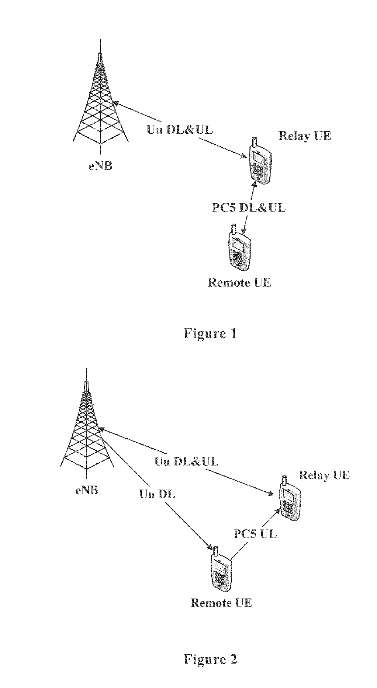
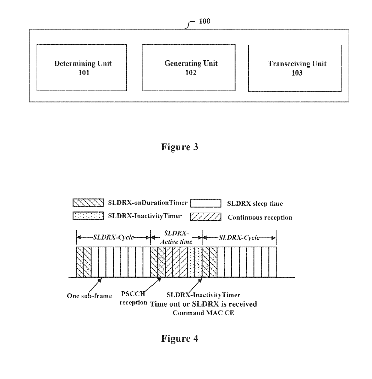
[0038]As described above, the smartphone can act as a relay device for the wearable device to reduce the energy consumption of the wearable device. Since a transmission data stream is usually a burst, that is, there is data transmission only within a certain period of time, the device serving as a receiving terminal can stop detecting when there is no data transmission, thereby achieving power saving, which is referred to as discontinuous reception (DRX). Especially when the wearable device has a lower data amount demand for transmission and reception, the application of DRX is more significant for reducing the device energy consumption and reducing the commercial cost. In the present application, DRX is for a sidelink, and thus it is referred to as Sidelink-DRX (SL-DRX) to be distinguished from DRX in LTE (the UE performs discontinuous reception of data from an eNB).
[0039]FIG. 3 shows a functional module block diagram of an electronic apparatus 100 for a network control terminal ac...
second embodiment
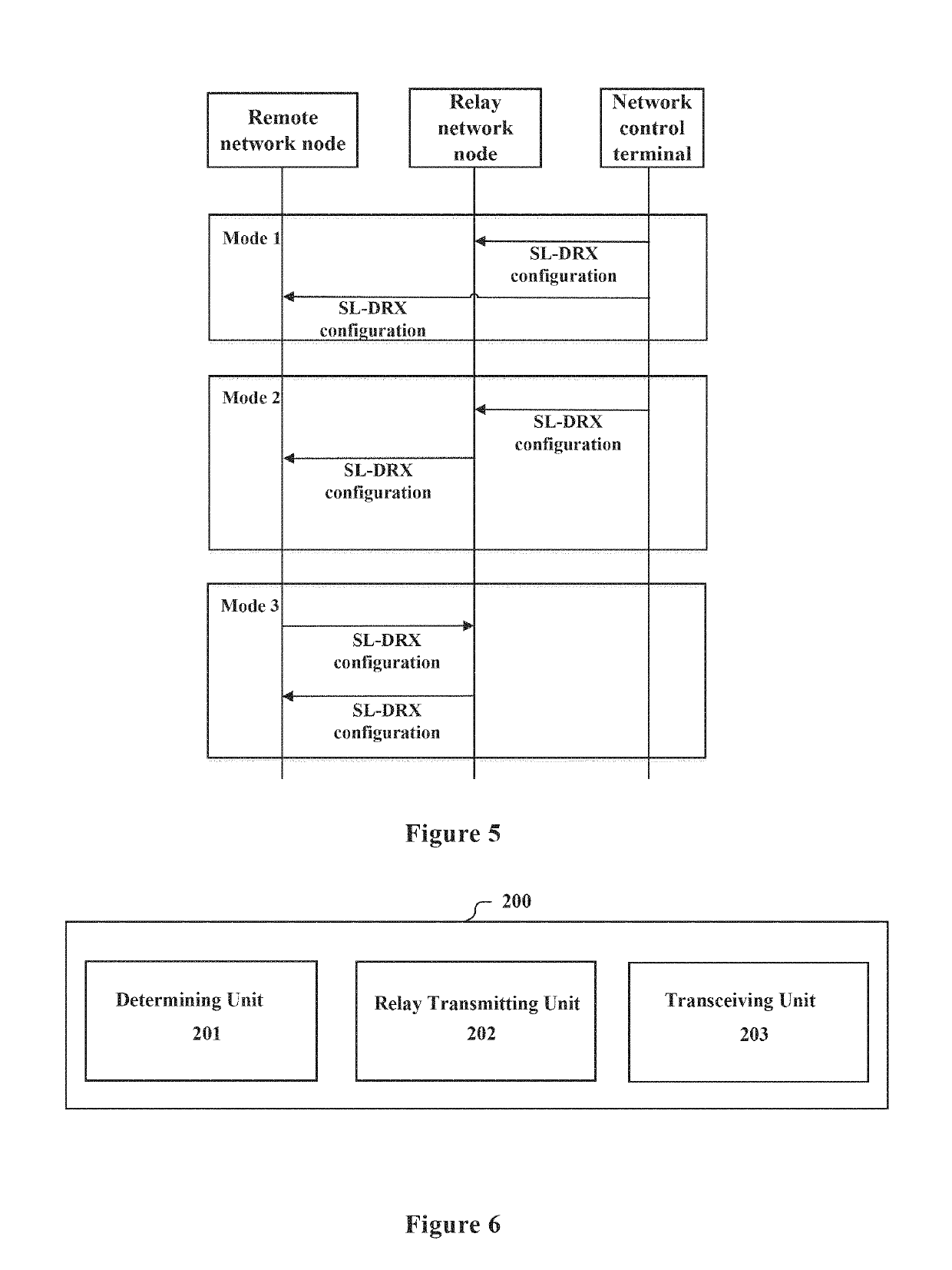
[0059]FIG. 6 shows a structural block diagram of an electronic apparatus 200 for a network node according to an embodiment of the present application, and the electronic apparatus 200 includes: a determining unit 201, configured to, with respect to a sidelink between the network node and one or more other network nodes, configure discontinuous reception SL-DRX for the network node and one or more other network nodes; and performing a relay transmission between the network node and the one or more other network nodes based on the SL-DRX configuration.
[0060]The network node in the present embodiment may be a relay network node, or may also be a remote network node. In the case of a relay network node, there may be a case where there is a sidelink between the relay network node and a plurality of remote network nodes, that is, a one-to-many relay.
[0061]For example, the determining unit 201 may determine the SL-DRX configuration based on the control signaling from the network control te...
third embodiment
[0072]After the SL-DRX is introduced on the sidelink, the length of the SLDRX-ActiveTime where the relay network node receives data varies with the scheduling decision and the success or failure of the decoding, and when the remote network node transmits data to the relay network node, it does not know about the downlink communication states of the relay network node and the network control terminal. Therefore, in some communication schemes such as FDD, it may happen that the relay network node receives data from the network control terminal simultaneously when it is in the SLDRX-ActiveTime. In this way, data conflicts may occur and the relay network node may lose data on one of the links. A similar problem exists for the remote network node capable of receiving data from the network control terminal and data from the relay network node. Therefore, in order to avoid conflicts occurring at the time of data reception and to maintain balance between high energy efficiency and quality o...
PUM
 Abstract
Description
Claims
Application Information
 - R&D
- Intellectual Property
- Life Sciences
- Materials
- Tech Scout
- Unparalleled Data Quality
- Higher Quality Content
- 60% Fewer Hallucinations
Browse by: Latest US Patents, China's latest patents, Technical Efficacy Thesaurus, Application Domain, Technology Topic, Popular Technical Reports.
© 2025 PatSnap. All rights reserved.Legal|Privacy policy|Modern Slavery Act Transparency Statement|Sitemap|About US| Contact US: help@patsnap.com


