Passive safety intraosseous device

a safety device and passive technology, applied in the field of passive safety intraosseous devices, can solve the problems of compromising the ability to provide such a necessary action, incurring time that is of enormous necessity, and suffering from cardiac arrest or other types of malady, so as to facilitate manual operation, avoid potential exposure, and simplify the effect of disposal

Inactive Publication Date: 2019-06-13
JUNE ACCESS IP LLC
View PDF0 Cites 3 Cited by
  • Summary
  • Abstract
  • Description
  • Claims
  • Application Information

AI Technical Summary

Benefits of technology

[0010]A distinct advantage of the versatile apparatus now disclosed is the provision of a drill with stylet / cannula implement that exhibits total passive safety to avoid any potential exposure to contaminated components subsequent to application of the cannula within a target patient's bone. Another advantage includes the ability to provide a potentially disposable drill / stylet combination that accords the ability to have the entirety of the device provided as a single portable structure, thus eliminating the need to locate separate component parts prior to utilization and simplified disposal of the same. Another advantage is the ability to provide a drill component that has a proper shape that allows for facilitated manual operation for stylet / cannula introduction if needed. Yet another advantage is the ability of the stylet to be retracted back within the drill subsequent to drilling completion and detachment from the cannula. Still another advantage of the overall device and system is the potential for a sensor to determine the exact moment of entry within the intermedullary space of a subject bone, thus eliminating the possibility of such a device from entering such a space too far or not far enough, maximizing the amount of space such a device permits fluid introduction and / or removal from the subject bone.

Problems solved by technology

Such a patient may be suffering from cardiac arrest or other type of malady at that moment requiring quick action to introduce necessary fluids / medicaments for treatment.
With an IV-based procedure, again, if the patient is situated in a difficult position for such IV access, or at least in terms of access at a proper and suitable vein for such a purpose, the ability to provide such a necessary action may be compromised.
Finding the vein, for instance, may be difficult and require multiple attempts by the emergency medical technician, incurring time that is of enormous necessity.
Guides may be provided at the skin surface for some degree of control and depth determinations, but the ability to properly operate and apply such a manual device has not proven effective and / or desirous in developed nations.
Relative speed of introduction is likewise then a potential drawback of this type of device.
Such gun-like delivery devices are, frankly, limited in their benefits to the industry simply because the user must properly hold and aim such a device while it basically shoots a cannula device through a subject patient's skin and into his or her bone.
Such a method has proven highly suspect at the emergency use level, primarily because of the difficulties in keeping the alignment, etc., in place correctly and, more importantly, the lack of control of the depth of introduction within the subject bone.
If employed with certain target bones, such a “shot” dart may crack certain bones, potentially causing potential problems such as leakage of intramedullary fluids or, more importantly, introduction within the bone of undesirable substances (not to mention significant pain for the subject patient, too).
Additionally, such a device may misfire, hitting undesired locations, may dislodge from a patient's bone readily particularly when the stylet is removed, or even fail to penetrate the target bone.
As such, the drawbacks of this type of intraosseous device are prevalent.
There are, however, significant drawbacks with such devices and procedures, namely the requirement for effective control prior to skin introduction; instances have occurred where the user attempts to set the stylet properly at the skin surface only to lose control and impale or at least scar the subject patient, even in non-emergency situations.
Also, the necessity of handling the extremely sharp stylet has proven difficult and hazardous, particularly after detachment from the cannula and most particularly in emergency situations.
Of further importance, if not the highest importance, however, is that whether in terms of the projectile or magnetically attached drill type (or any other types within the prior art, including spring-loaded drills, sternum-applied drilling stylet / cannula implements, etc.) there is always an issue related to the potential for contamination of the stylet and high potential for contact with a user, patient, or other bystander during utilization.
However, in any situation typically provided as of today, the lack of automatic coverage and requirement of active removal with such exposure, no matter how prolonged it may be, leaves too much of a chance for transfer of contamination.
Furthermore, with the reusable drill implement of the magnetically attached stylet / cannula method and device, such a drill is potentially contaminated after each use.
Additionally, in emergency situations, such a magnetically attached device requires the actual locating of, unpacking of, and applying (attaching) of such a stylet / cannula implement to a potentially previously contaminated and potentially questionable power level for sufficient operation, such that clear difficulties in utilization thereof exist.

Method used


Image

  • Passive safety intraosseous device
  • Passive safety intraosseous device
  • Passive safety intraosseous device

Examples


Embodiment Construction

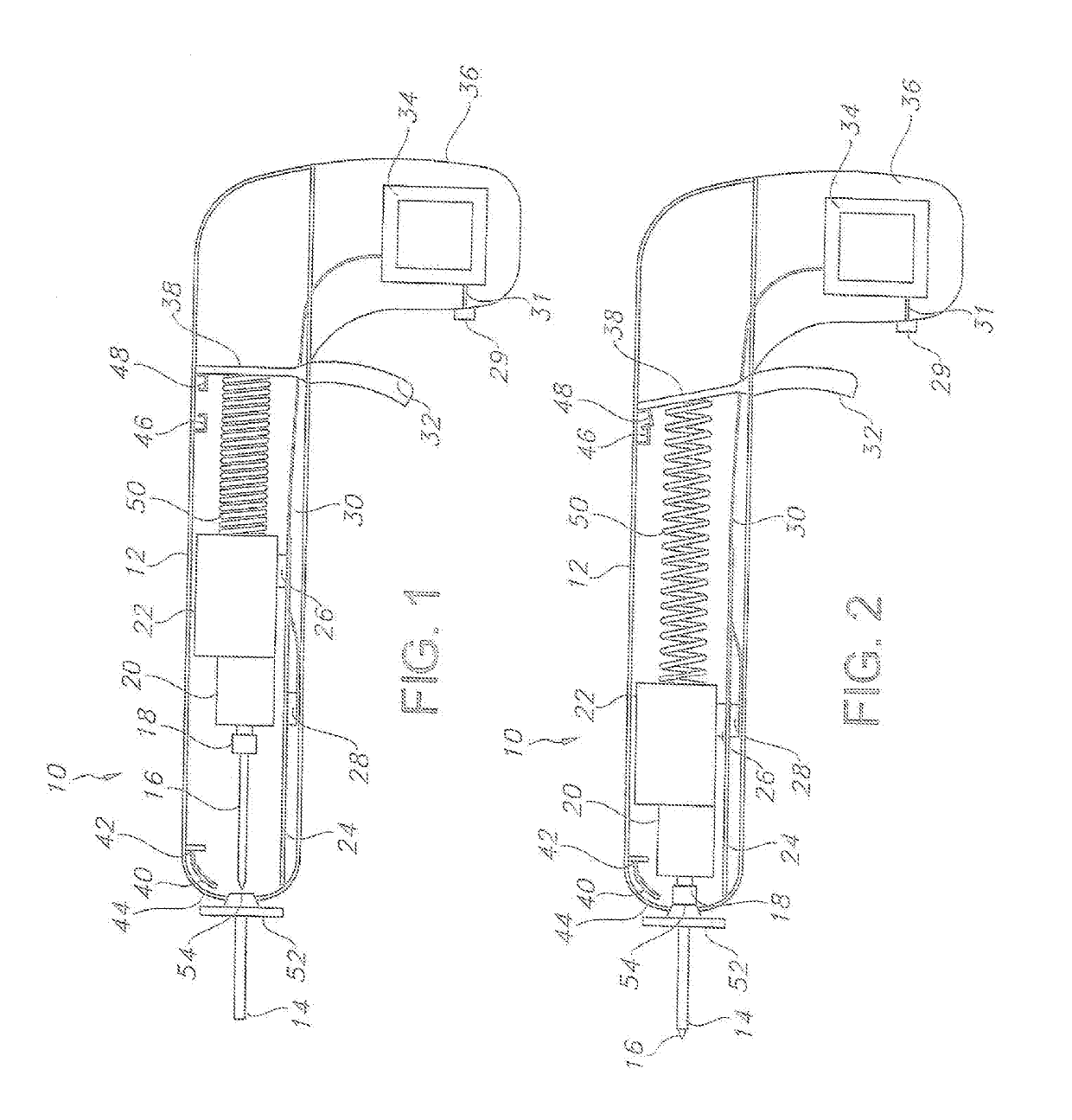
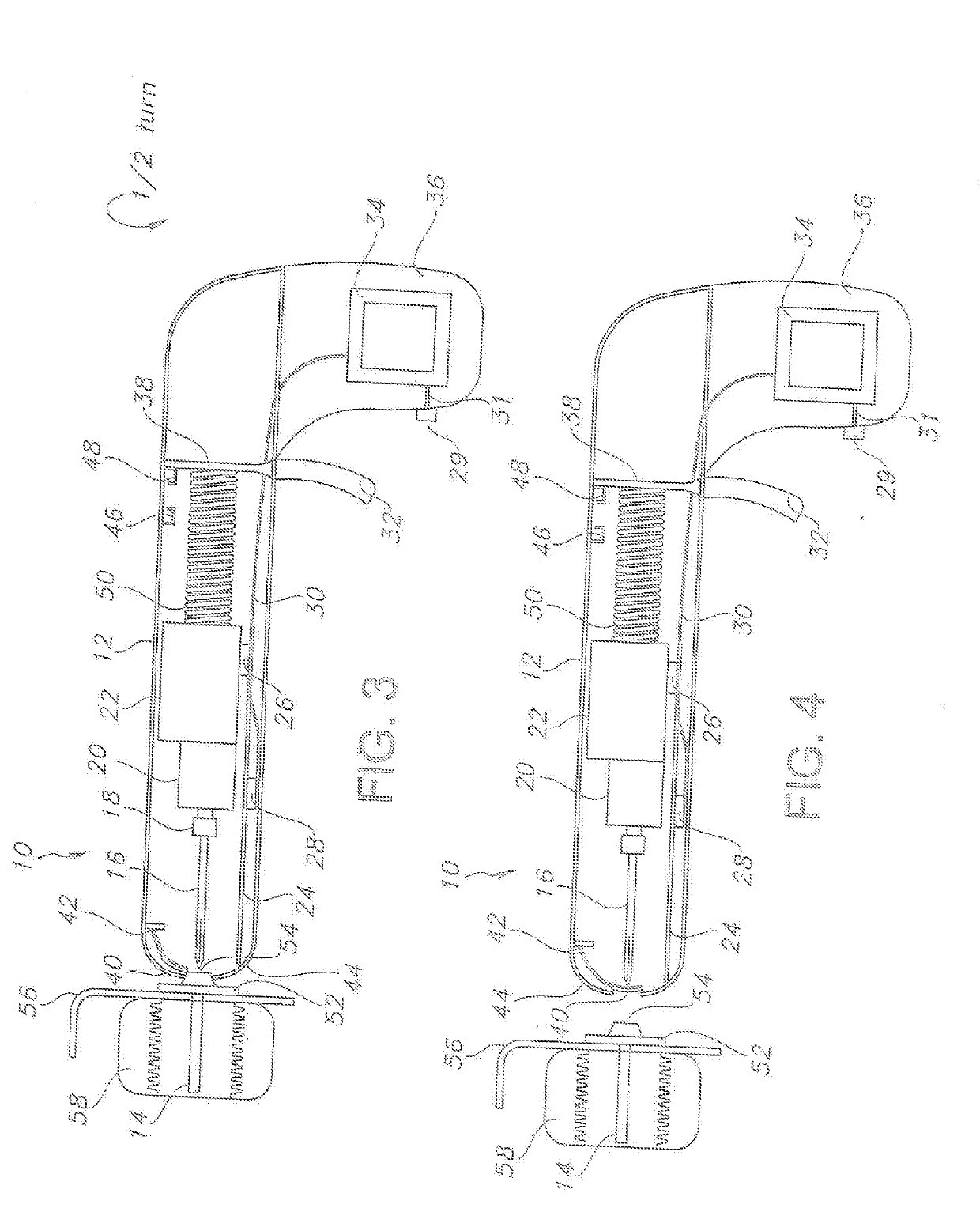
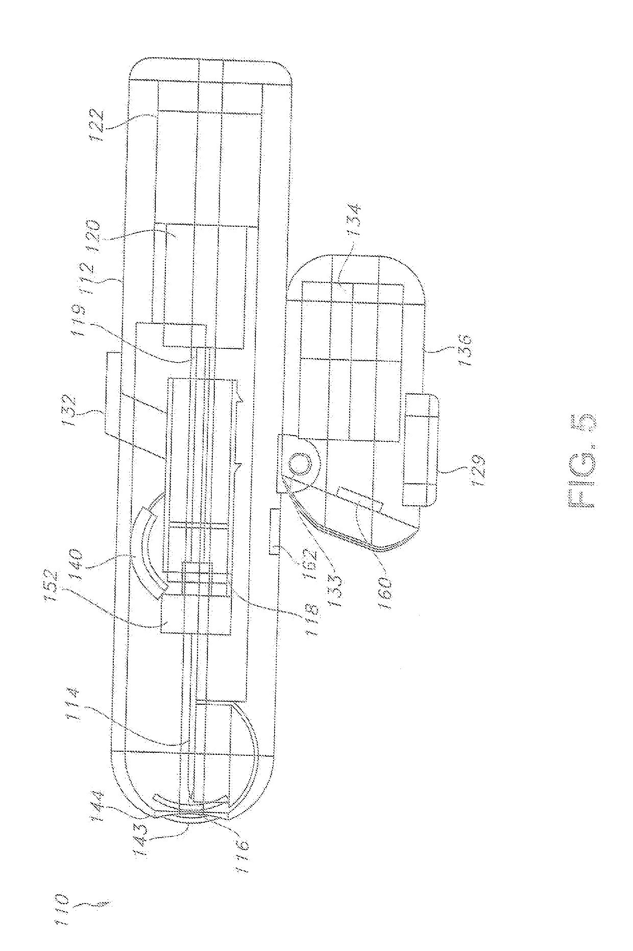
[0052]Reference now should be made to the drawings, presented as non-limiting possible embodiments in accordance with the descriptions provided above. The ordinarily skilled artisan would fully understand the breadth and scope intended herein in relation to the following potentially preferred types.

[0053]It will be understood that, although the terms first, second, third, etc. may be used herein to describe various elements, these elements should not be limited by these terms. These terms are only used to distinguish one element from another element. Thus, a first element discussed below could be termed a second element without departing from the teachings of the present disclosure.

[0054]The terminology used herein is for the purpose of describing particular embodiments only and is not intended to be limiting. As used herein, the singular forms “a”, “an”, and “the” are intended to include the plural forms as well, unless the context clearly indicates otherwise. It will be further un...


PUM


Abstract

A portable and passive safety intraosseous device to allow for direct introduction of medications, etc., within the intermedullary space of a subject patient's bone or, if needed, the removal of certain substances from such a subject patient's bone. Such a device permits direct drilling and placement of a cannula within the subject bone with access external to the subject patient's skin, permitting, as well, connection of a tube for such introduction / removal purposes. The ability to provide a passive safety unit allows for facilitated utilization in, for instance, emergency situations with the entire device provided for utilization thereof. The device includes a drilling component with a permanently attached stylet and a removable cannula, a power supply for a single drilling operation, a mechanism to draw the stylet back into the drill component after use and disengagement from the cannula, and an automatic closure that activates with the separation of the cannula.

Description

CROSS-REFERENCE TO RELATED APPLICATIONS[0001]This application claims the benefit of copending U.S. Provisional Patent Application No. 62 / 556,397, filed on Sep. 9, 2017, and 62 / 566,498, filed on Oct. 1, 2017. The entirety of both provisional applications are herein incorporated by reference.FIELD OF THE INVENTION[0002]The disclosure relates to a portable and passive safety intraosseous device to allow for direct introduction of medications, etc., within the intermedullary space of a subject patient's bone or, if needed, the removal of certain substances from such a subject patient's bone. Such a device permits direct drilling and placement of a cannula within the subject bone with access external to the subject patient's skin, permitting, as well, connection of a tube for such introduction / removal purposes. The ability to provide a passive safety unit allows for facilitated utilization in, for instance, emergency situations with the entire device provided for utilization thereof. The...

Claims


Application Information

Patent Timeline
Patent Type & Authority Applications(United States)
IPC IPC(8): A61B17/34A61B17/16A61B17/88
CPCA61B17/3472A61B17/1615A61B17/3421A61B17/8805A61B17/164A61B17/3401A61B17/8847A61B10/025A61B17/1626A61B17/1628A61B17/1671A61B2017/0046A61B2017/00477A61B2017/00734A61B2017/291A61B2090/064A61B2090/065A61B2090/0801A61B2090/08021A61B17/1622A61B2017/2927A61B2090/0811A61B17/8811A61B17/8819A61B17/1637A61M39/10A61M2210/02A61B17/3415A61B17/3423A61B90/08A61B2090/0808A61B90/30A61B17/17A61B17/3496A61B2017/00115A61B2017/0023
Inventor COPPEDGE, BILLIETESREAU, KEVINNEEL, MICHAELPARKS, WILLIAM
Owner JUNE ACCESS IP LLC
Why Eureka
Try Eureka