
Flexible touch screen panel and method of manufacturing the same

Active Publication Date: 2019-06-13
LG DISPLAY CO LTD
View PDF6 Cites 6 Cited by
  • Summary
  • Abstract
  • Description
  • Claims
  • Application Information

AI Technical Summary

Benefits of technology

The present patent provides a flexible touch screen panel that can be attached to a surface of a flexible display device and give a touch input function. The panel prevents wire defects due to over-etching and / or undercutting of the flexible substrate, and maintains an insulation property of the insulating film that insulates the electrodes from the bridge, preventing short-circuit between the touch electrodes and wire defects. The panel also has a robust structure even after repeated bending operations.

Problems solved by technology

The liquid crystal display and the plasma display panel have limitations in the development of self-luminous elements having high flexibility and elasticity, and thus they are limited in applications as flexible display devices.
However, use of a separate input device, such as the keyboard and the mouse, causes the inconvenience of acquiring knowledge about how to use it and occupying additional space, so that it is difficult to improve completeness of a product.

Method used


Image

  • Flexible touch screen panel and method of manufacturing the same
  • Flexible touch screen panel and method of manufacturing the same
  • Flexible touch screen panel and method of manufacturing the same

Examples


first embodiment

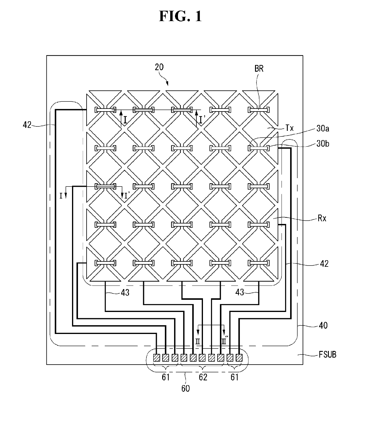
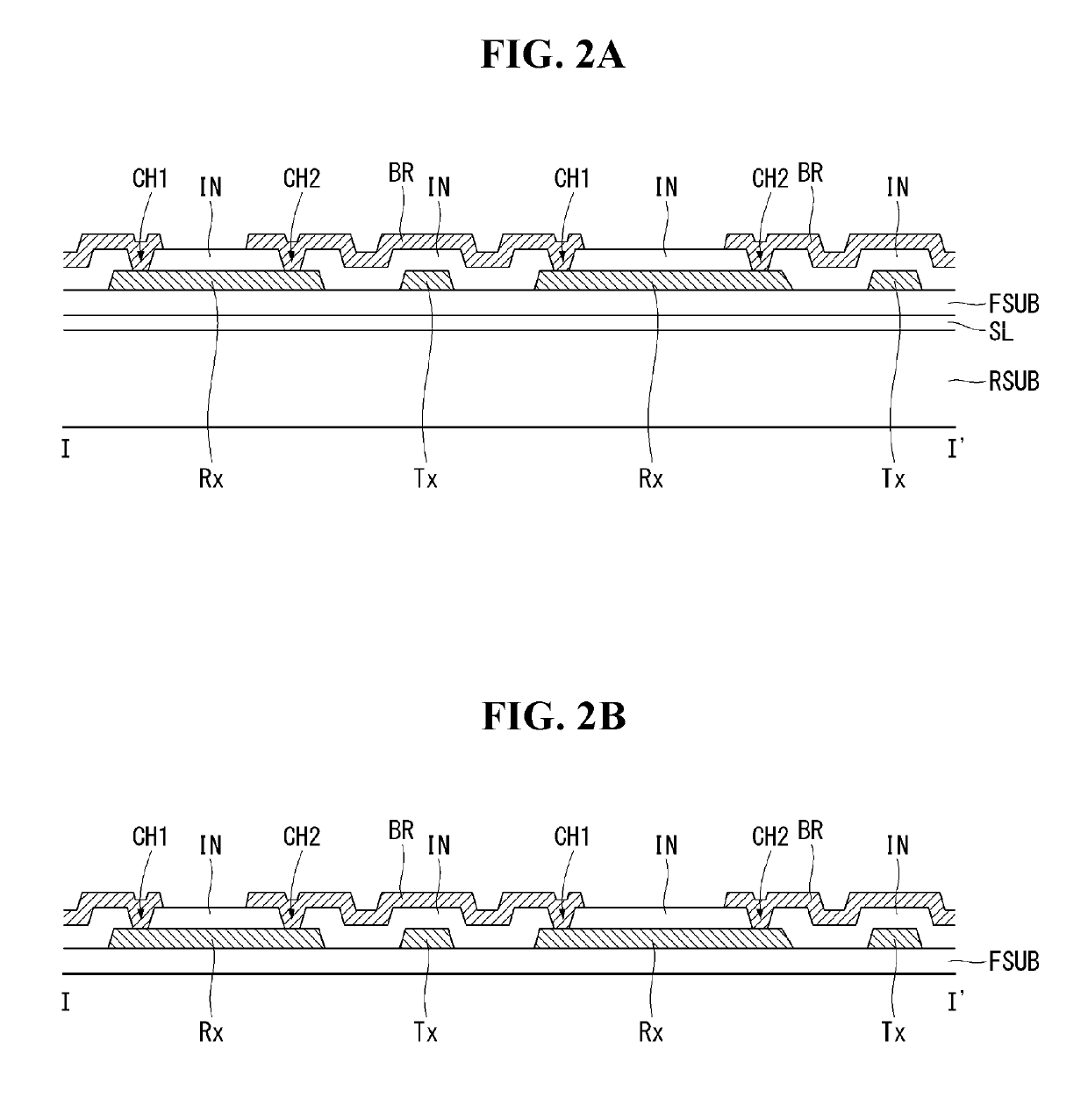
[0032]Hereinafter, referring to FIGS. 1, 2A and 2B, a flexible touch screen panel according to a first embodiment of the present disclosure will now be described. FIG. 1 is a plan view illustrating a structure of a flexible touch screen panel according to a first embodiment of the present disclosure. FIGS. 2A and 2B are cross-sectional views illustrating a manufacturing process of a flexible touch screen panel according to a first embodiment of the present disclosure, taken along a line I-I′ of FIG. 1.

[0033]The flexible touch screen panel according to the first embodiment of the present disclosure includes an electrode part 20, a routing wire part 40, and a pad part 60 formed on a flexible substrate FSUB.

[0034]The electrode part 20 includes first electrodes Rx and second electrodes Tx formed on the flexible substrate FSUB. The first electrodes Rx are arranged in parallel in a first direction (e.g., an X-axis direction), and the second electrodes Tx are arranged to cross the first el...

second embodiment

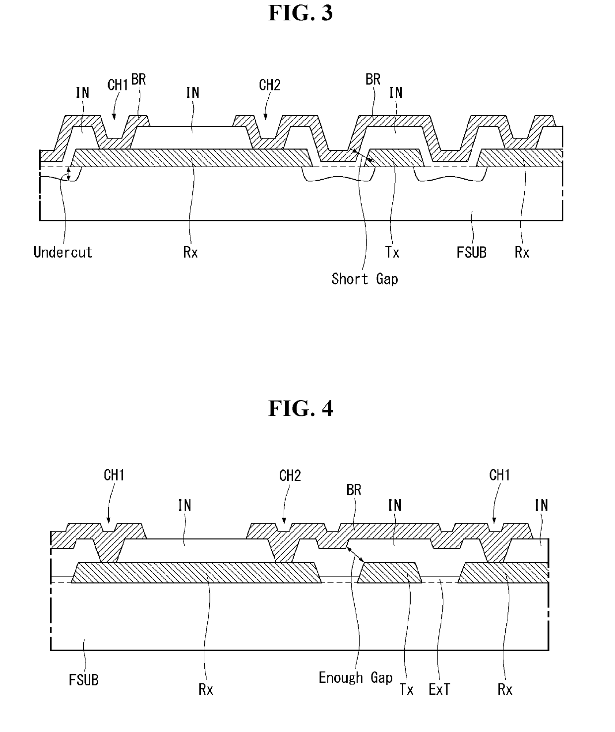
[0045]In the first embodiment described above, in the process of forming the first and second electrodes Rx and Tx on the flexible substrate FSUB, over-etching and / or undercutting phenomenon may occur in the flexible substrate FSUB. Hereinafter, an influence of the over-etching and / or undercutting occurrence will be described with reference to FIG. 3. FIG. 3 is an enlarged cross-sectional view illustrating a structure of wire defects due to over-etching and / or undercutting of a flexible substrate that can occur in a first embodiment of the present disclosure.

[0046]After depositing a metallic material on the flexible substrate FSUB, a first electrode Rx and a second electrode Tx are formed by patterning the metallic material by photolithography. At this time, over-etching may occur due to a material characteristic of the flexible substrate FSUB. Also, an undercutting phenomenon that penetrates to the bottom of a metal layer may occur at edge parts of the first electrode Rx and the se...


PUM


Abstract

A flexible touch screen panel can include a flexible substrate including a plurality of trenches; first electrodes and second electrodes disposed in the plurality of trenches in the flexible substrate; an insulating film covering the first electrodes and the second electrodes; a contact hole in the insulating film to expose at least one of the first electrodes; and a bridge disposed on the insulating film, the bridge electrically connecting two of the first electrodes to each other through the contact hole.

Description

[0001]This application claims the priority benefit of Korean Patent Application No. 10-2017-0170489 filed in the Republic of Korea on Dec. 12, 2017, the entire disclosure of which is hereby incorporated by reference herein for all purposes.BACKGROUND OF THE INVENTIONField of the Invention[0002]The present disclosure relates to a flexible touch screen panel that is disposed in a flexible display device and gives a touch input function to the display device, and a method of manufacturing the same. More particularly, the present disclosure relates to a flexible touch screen panel having a structure for preventing wire defects due to over-etching and / or undercutting of a flexible substrate in forming a metal wire on the flexible substrate, and a method of manufacturing the same.Discussion of the Related Art[0003]Recently, various flat panel displays capable of reducing weight and volume, which are disadvantages of cathode ray tubes, have been developed. The flat panel displays may be im...

Claims


Application Information

Patent Timeline
IPC IPC(8): G06F3/041
CPCG06F3/041G06F2203/04102G06F2203/04103G06F2203/04111G06F3/0446G06F3/0443
Inventor MOON, YOUNGGYU
Owner LG DISPLAY CO LTD
Learn More