Method for estimating 6-dof relative displacement using vision-based localization and apparatus therefor

Active Publication Date: 2019-06-13
KOREA ADVANCED INST OF SCI & TECH
View PDF0 Cites 2 Cited by
  • Summary
  • Abstract
  • Description
  • Claims
  • Application Information

AI Technical Summary

Benefits of technology

The patent is about a method and apparatus for accurately estimating the location of a moving object in an image and using it to precisely assemble other objects using visual information. This can be useful in construction and industrial settings to reduce construction periods and improve product quality. The technology can also be used for location tracking and assembly of objects in real-time, using pre-cast concrete members as an example.

Problems solved by technology

Because the cast-in-place method casts concrete in an opened environment, there is a disadvantage that additional cost is often incurred to re-cast concrete when a concrete member of desired quality is not obtained.
Also, when constructing bridges in large cities, detours are made or driveways are blocked, which greatly affects the volume of traffic.
Therefore, although it is important to construct fast, time delay occurring in the cast-in-place method occurs.
Despite many advantages, there is a disadvantage in the PC method.

Method used


Image

  • Method for estimating 6-dof relative displacement using vision-based localization and apparatus therefor
  • Method for estimating 6-dof relative displacement using vision-based localization and apparatus therefor
  • Method for estimating 6-dof relative displacement using vision-based localization and apparatus therefor

Examples


Embodiment Construction

[0052]Hereinafter, some example embodiments will be described in detail with reference to the accompanying drawings. Regarding the reference numerals assigned to the elements in the drawings, it should be noted that the same elements will be designated by the same reference numerals, wherever possible, even though they are shown in different drawings.

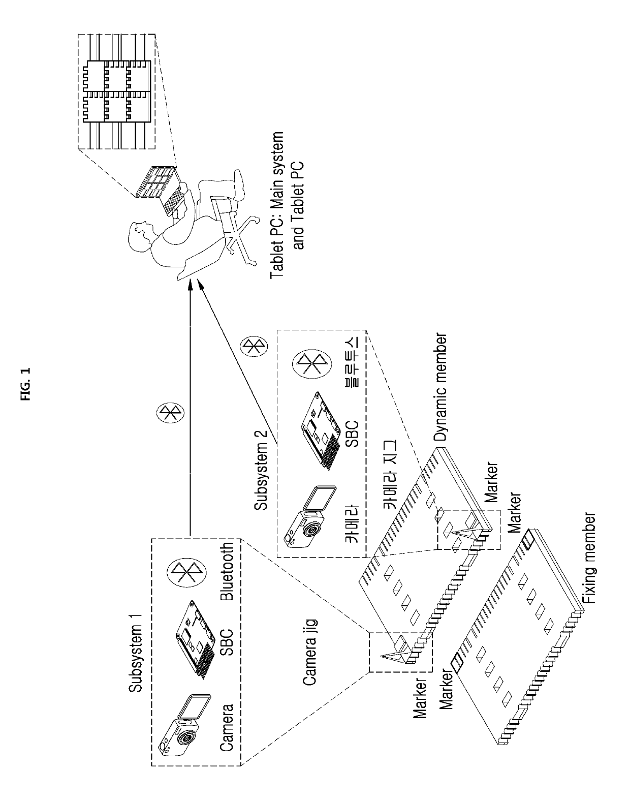
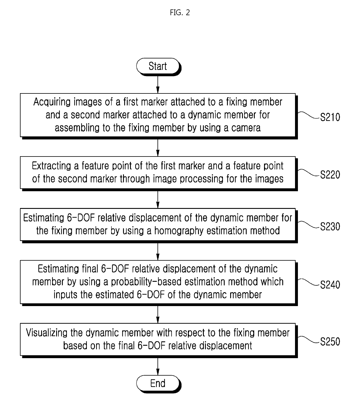
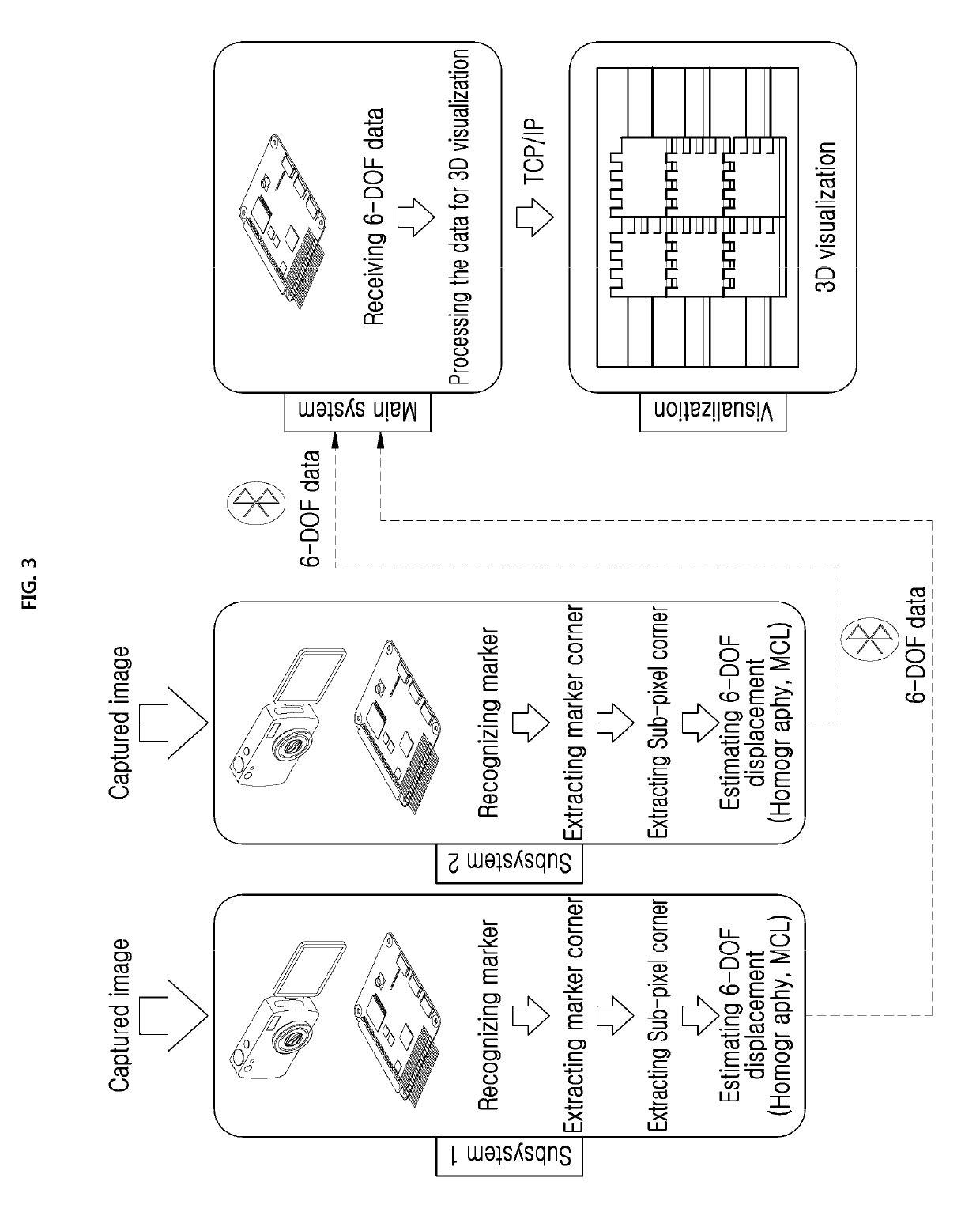
[0053]The example embodiments of the present invention have a main point for precisely estimating a location of a dynamic member when occlusion of a marker by a dynamic member, for example, a member transported by a crane operator (hereinafter, “dynamic member”) or blur on a camera image by member moving occurs.

[0054]Here, the present invention may precisely estimate relative displacement of a dynamic member by determining any method among a homography estimation method and a probability-based location estimation method, for example, MCL (Monte Carlo Localization) method depending on how precisely a marker corner point (or feature point...


PUM


Abstract

A method for estimating 6-DOF relative displacement using vision-based localization and apparatus therefor are disclosed. A method for estimating 6-DOF relative displacement may include acquiring images of a first marker attached to a fixing member and a second marker attached to a dynamic member for assembling to the fixing member by using a camera, extracting a feature point of the first marker and a feature point of the second marker through image processing for the acquired images, and estimating 6-DOF relative displacement of the dynamic member for the fixing member based on the extracted feature point of the first marker and feature point of the second marker.

Description

[0001]This application claims the priority benefit of Korean Patent Application No. 10-2017-0170418, filed on Dec. 12, 2017, and Korean Patent Application No. 10-2018-0043199, filed on Apr. 13, 2018, in the Korean Intellectual Property Office, the disclosure of which is incorporated herein by reference.BACKGROUND1. Field of the Invention[0002]The following example embodiments relate to a technology for estimating 6-DOF relative displacement, and more particularly, a method for estimating 6-DOF relative displacement of a dynamic member for a fixing member (or static member) by using a vision-based localization and an apparatus therefor.2. Description of the Related Art[0003]As recent high growth of economy around the world, fast goods transport is important topic and bridges are actively constructed.[0004]To meet steady demand for bridge construction, methods of constructing bridge have been developed. Generally, a cast-in-place method casting concrete at a site has been used in cons...

Claims


Application Information

Patent Timeline
IPC IPC(8): G06K9/46G06T5/20G06T7/73
CPCG06K9/46G06T5/20G06T7/74G06T2207/30204G06T2207/20028G06T5/73
Inventor MYEONG, HYEONCHOI, SU YOUNGMYEONG, WANCHEOL
Owner KOREA ADVANCED INST OF SCI & TECH
Why Eureka
Try Eureka