

Smoke detector chamber boundary surfaces
a detector chamber and boundary surface technology, applied in the field of optical boundary surfaces, can solve the problems of inability to predict the type of fire one may have in a home or when, ions will attach to particles, and cannot carry current, so as to prevent ambient light, reduce the value, and reduce the effect of ions
- Summary
- Abstract
- Description
- Claims
- Application Information
AI Technical Summary
Benefits of technology
Problems solved by technology
Method used
Image

Examples
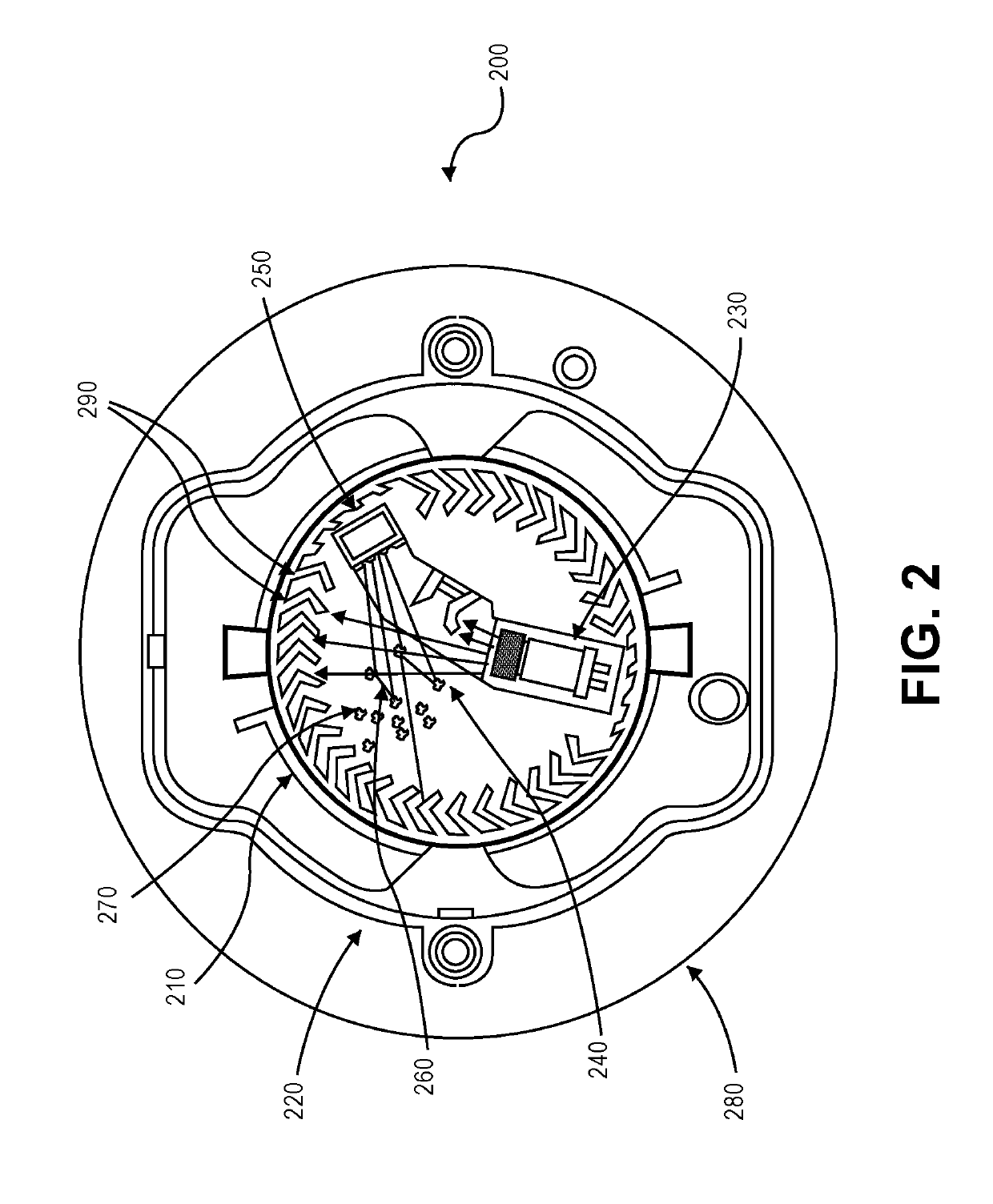
case molding 290
[0083]Case molding 290 is a substrate in some embodiments providing structure to for attaching detector cover 220 and optical chamber 210 thereto. Typically, it is an object of optical smoke detectors to allow the ingress of smoke from the surrounding air / environment while rejecting the ambient light emanating from same. Generally speaking, detector cover 220 and optical chamber 210 attempt to serve these purposes.
[0084]That is, detector cover 220 has two ports (e.g., ingress and egress) for gas / smoke passage, while optical chamber 210 substantially surrounds the detector interior preventing most ambient light to enter. Detector cover 220 and optical chamber 210 are made of an opaque polymer and / or lossy material having a thickness much greater than the average skin depth, according to some embodiments of the present invention. High conductivity (mirrored) or any other suitable material, e.g., metal, semi-metallic, composite, are also not beyond the scope of the present disclosure.
[...
PUM
| Property | Measurement | Unit |
|---|---|---|
| diameter | aaaaa | aaaaa |
| diameter | aaaaa | aaaaa |
| temperature | aaaaa | aaaaa |
Abstract
Description
Claims
Application Information