Image processing apparatus, image processing method, and storage medium having program stored therein
a technology of image processing and image quality, applied in the field of image processing apparatus, can solve the problems of not being able to predict a time and a place, and not being able to configure in advance a large-capacity public-oriented communication infrastructure, so as to suppress the lowering of image quality and reduce the network bandwidth necessary
- Summary
- Abstract
- Description
- Claims
- Application Information
AI Technical Summary
Benefits of technology
Problems solved by technology
Method used
Image
Examples
first example embodiment
[0052]«Configuration»
[0053]Next, a first example embodiment according to the present invention is described with reference to the drawings.
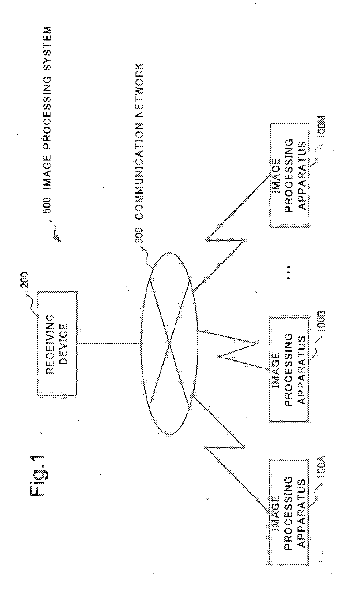
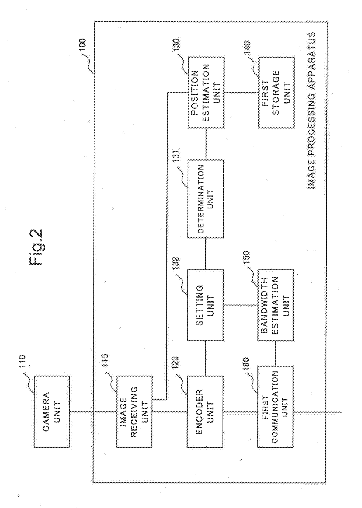
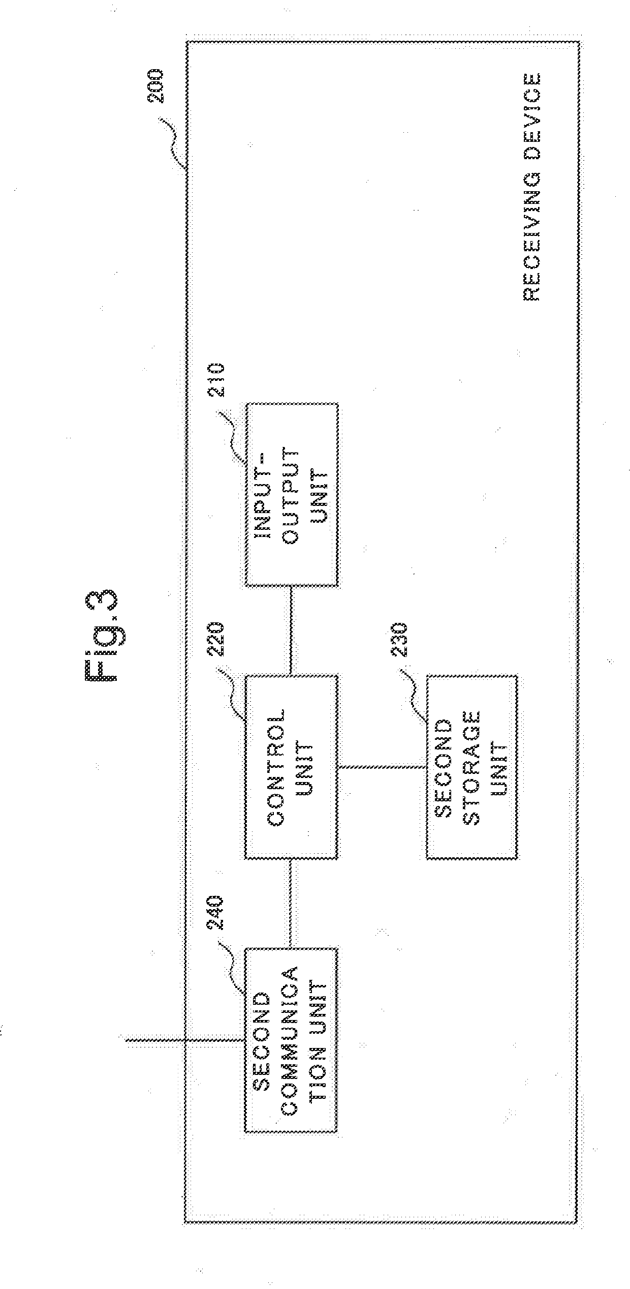
[0054]FIG. 1 is a block diagram illustrating a configuration example of an image processing system 500 according to the first example embodiment of the present invention. The image processing system 500 includes one or more image processing apparatuses 100 and a receiving device 200. The one or more image processing apparatuses 100 and the receiving device 200 may be communicably connected one another via a communication network 300. In the example illustrated in FIG. 1, as an example of the image processing apparatuses 100, image processing apparatuses 100A, 100B, . . . , and 100M are illustrated. The image processing apparatuses 100A, 100B, . . . , and 100M may have a common configuration illustrated as a configuration of the image processing apparatus 100 in the following. In the following, the image processing apparatuses 100A, 100B, . . . , ...
second example embodiment
[0144]«Configuration»
[0145]Next, an image processing system 501 in a second example embodiment according to the present invention is described in detail with reference to the drawings.
[0146]FIG. 9 is a block diagram illustrating a configuration example of the image processing system 501 in the present example embodiment. The image processing system 501 in the present example embodiment includes one or more image processing apparatuses 101 and a receiving device 200. The image processing apparatuses 101 are communicably connected to the receiving device 200 via a communication network 300.
[0147]When comparison is made with respect to the image processing system 500 in the first example embodiment illustrated in FIG. 4, the image processing system 501 in the present example embodiment includes the image processing apparatuses 101, in place of the image processing apparatuses 100. The receiving device 200 and the communication network 300 are respectively the same as the receiving devi...
third example embodiment
[0186]«Configuration»
[0187]Next, a third example embodiment of the present invention is described in detail with reference to the drawings.
[0188]FIG. 13 is a block diagram illustrating a configuration example of an image processing system 502 in the present example embodiment. The image processing system 502 in the present example embodiment includes one or more image processing apparatuses 102 and a receiving device 202. Each of the one or more image processing apparatuses 102 is communicably connected to the receiving device 202 via a communication network 300. When comparison is made with respect to the image processing system 500 in the first example embodiment illustrated in FIG. 4, the image processing system 502 in the present example embodiment includes the image processing apparatuses 102 in place of the image processing apparatuses 100, and includes the receiving device 202 in place of the receiving device 200. The image processing system 502 in the present example embodim...
PUM
 Abstract
Description
Claims
Application Information
 - R&D
- Intellectual Property
- Life Sciences
- Materials
- Tech Scout
- Unparalleled Data Quality
- Higher Quality Content
- 60% Fewer Hallucinations
Browse by: Latest US Patents, China's latest patents, Technical Efficacy Thesaurus, Application Domain, Technology Topic, Popular Technical Reports.
© 2025 PatSnap. All rights reserved.Legal|Privacy policy|Modern Slavery Act Transparency Statement|Sitemap|About US| Contact US: help@patsnap.com


