
Method and apparatus for protection switching in ring network

a protection switching and ring network technology, applied in data switching networks, frequency-division multiplexes, instruments, etc., can solve the problems of traffic overshoot phenomenon, rapid protection switching, and large network bandwidth, and achieve the effect of reducing the network bandwidth necessary

Inactive Publication Date: 2010-09-09
ELECTRONICS & TELECOMM RES INST
View PDF8 Cites 5 Cited by
  • Summary
  • Abstract
  • Description
  • Claims
  • Application Information

AI Technical Summary

Benefits of technology

[0008]An embodiment of the present invention is directed to a method and apparatus for protection switching in a ring network, which are capable of reducing the network bandwidth necessary for rapid protection switching in the case of a failure.
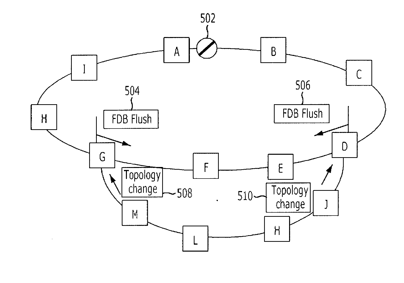
[0009]Another embodiment of the present invention is directed to a method and apparatus for performing protection switching in a ring network, which are capable of reducing the time necessary for protection switching and efficiently performing the protection switching by flushing the FDB of a limited range of nodes of an upper ring, not its all nodes, when a failure occurs in a lower ring of the ring network.

Problems solved by technology

Such flushing of the FDB of all nodes of the major ring (or upper sub-ring) causes a traffic overshoot phenomenon.
As a result, rapid protection switching in the case of a failure requires a larger network bandwidth.

Method used


Image

  • Method and apparatus for protection switching in ring network
  • Method and apparatus for protection switching in ring network
  • Method and apparatus for protection switching in ring network

Examples


Embodiment Construction

[0023]Exemplary embodiments of the present invention will be described below in more detail with reference to the accompanying drawings. The present invention may, however, be embodied in different forms and should not be constructed as limited to the embodiments set forth herein. Rather, these embodiments are provided so that this disclosure will be thorough and complete, and will fully convey the scope of the present invention to those skilled in the art. Throughout the disclosure, like reference numerals refer to like parts throughout the various figures and embodiments of the present invention.

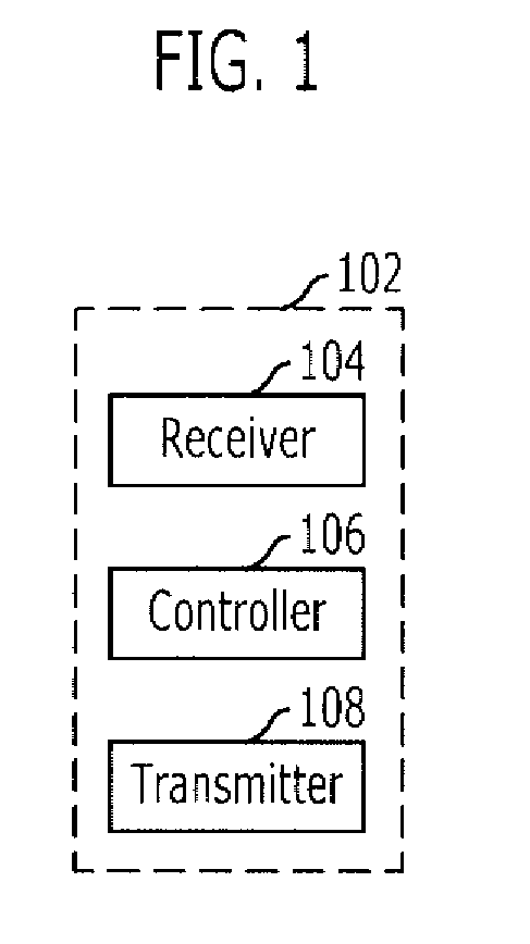
[0024]FIG. 1 is a configuration diagram of an apparatus for protection switching in a ring network in accordance with a specific embodiment of the present invention.

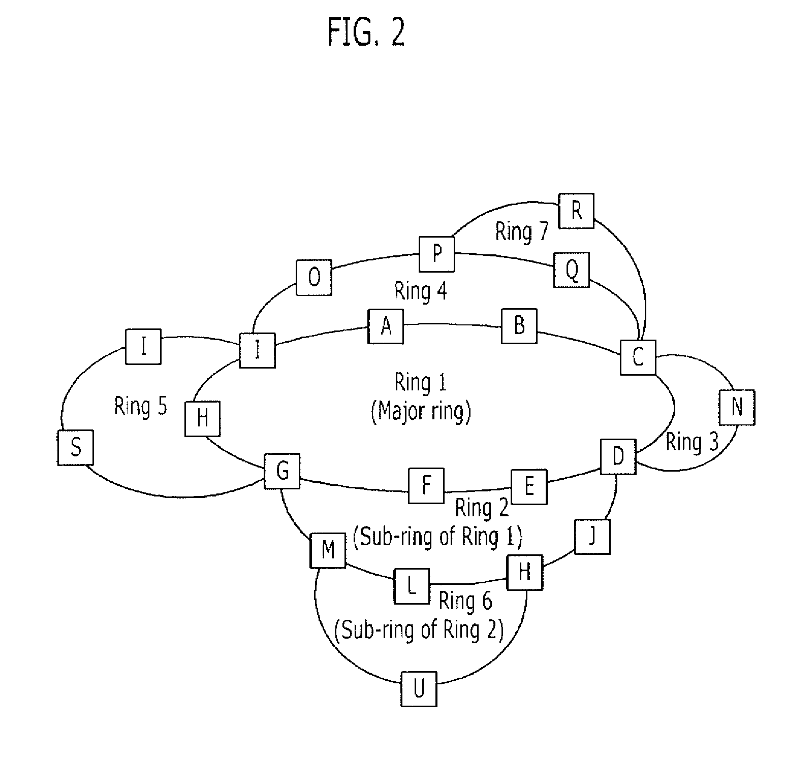
[0025]When assuming an interconnection between a major ring and a sub-ring or between an upper sub-ring and a lower sub-ring, the major ring or the upper sub-ring will be referred to as an upper ring network or simply an upper ...


PUM


Abstract

A method and apparatus for protection switching in a ring network are provided. A method for protection switching in a ring network, which includes a first ring network having first and second connection nodes and a second ring network connected with the first ring network through the first and second connection nodes, includes: receiving, by the first connection node, first and second R-APS messages transmitted from nodes belonging to the first ring network; determining, by the first connection node, the position of closure in the first ring network by using the first and second R-APS messages and topology information; receiving, by the first connection node, a topology change signal transmitted from the second ring network; and transmitting, by the first connection node, an FDB flush message with reference to the position of closure.

Description

CROSS-REFERENCE(S) TO RELATED APPLICATIONS[0001]The present application claims priority of Korean Patent Application No. 10-2009-0012610, filed on Feb. 16, 2009, which is incorporated herein by reference in its entirety.BACKGROUND OF THE INVENTION[0002]1. Field of the Invention[0003]Exemplary embodiments of the present invention relate to a method and apparatus for protection switching in a ring network.[0004]2. Description of Related Art[0005]A ring network refers to a network in which both ports belonging to each node are connected to ports of adjacent nodes, respectively, in a ring shape. In such a ring network, a specific one of ports belonging to the ring is closed to prevent loop formation when traffic is transmitted. If the ring network fails, ports that have been closed are opened, and ports of the failed nodes are closed, eventually changing the topology of the ring network. In order to correctly transmit packets according to the changed network topology, each node belongin...

Claims


Application Information

Patent Timeline
Patent Type & Authority Applications(United States)
IPC IPC(8): G06F11/00
CPCH04L12/437H04L12/4637H04L43/0811H04L45/28H04L45/22
Inventor RYOO, JEONG-DONGLEE, SANG-MINKIM, DAEUBLEE, BHUM-CHEOL
Owner ELECTRONICS & TELECOMM RES INST
Learn More