
Tiled display device and tiling apparatus therefor

Active Publication Date: 2019-06-20
LG DISPLAY CO LTD
View PDF5 Cites 15 Cited by
  • Summary
  • Abstract
  • Description
  • Claims
  • Application Information

AI Technical Summary

Benefits of technology

The invention is a tiling apparatus that allows for easy attachment and detachment of a display panel without the need for additional mechanical coupling. The apparatus includes two magnets: one for attaching the panel and one for detaching it. The apparatus can be easily actuated with a handle to quickly and easily disassemble the tiled display device. The technical effect of this invention is to simplify the process of attaching and detaching display panels from tiled display devices.

Problems solved by technology

However, such electronic display boards or screens should be manufactured to be several hundreds of inches or more in size, and it is difficult to manufacture a a single display device of such size using current technology.
However, there are the following problems in such a conventional tiled display device.
First, since the tiled display device has a plurality of display panels attached together, when the gap between display panels is equal to or larger than a predetermined size, the seam at a boundary region may be undesirably perceived by viewers.
In this regard, in the case of tiling such a large-sized display panel, it is difficult for a worker or installation staff to tile or attach each display panel at a precise position due to the weight thereof and thus the gap between display panels may be equal to or larger than the predetermined size.
Second, it takes a long time to assemble and disassemble the tiled display device.
However, because it takes a lot of time and effort (several days are required) to assemble and disassemble the display panels which are large-sized and heavy, with the coupling elements such as screws, inconvenience is caused in use.

Method used


Image

  • Tiled display device and tiling apparatus therefor
  • Tiled display device and tiling apparatus therefor
  • Tiled display device and tiling apparatus therefor

Examples


first embodiment

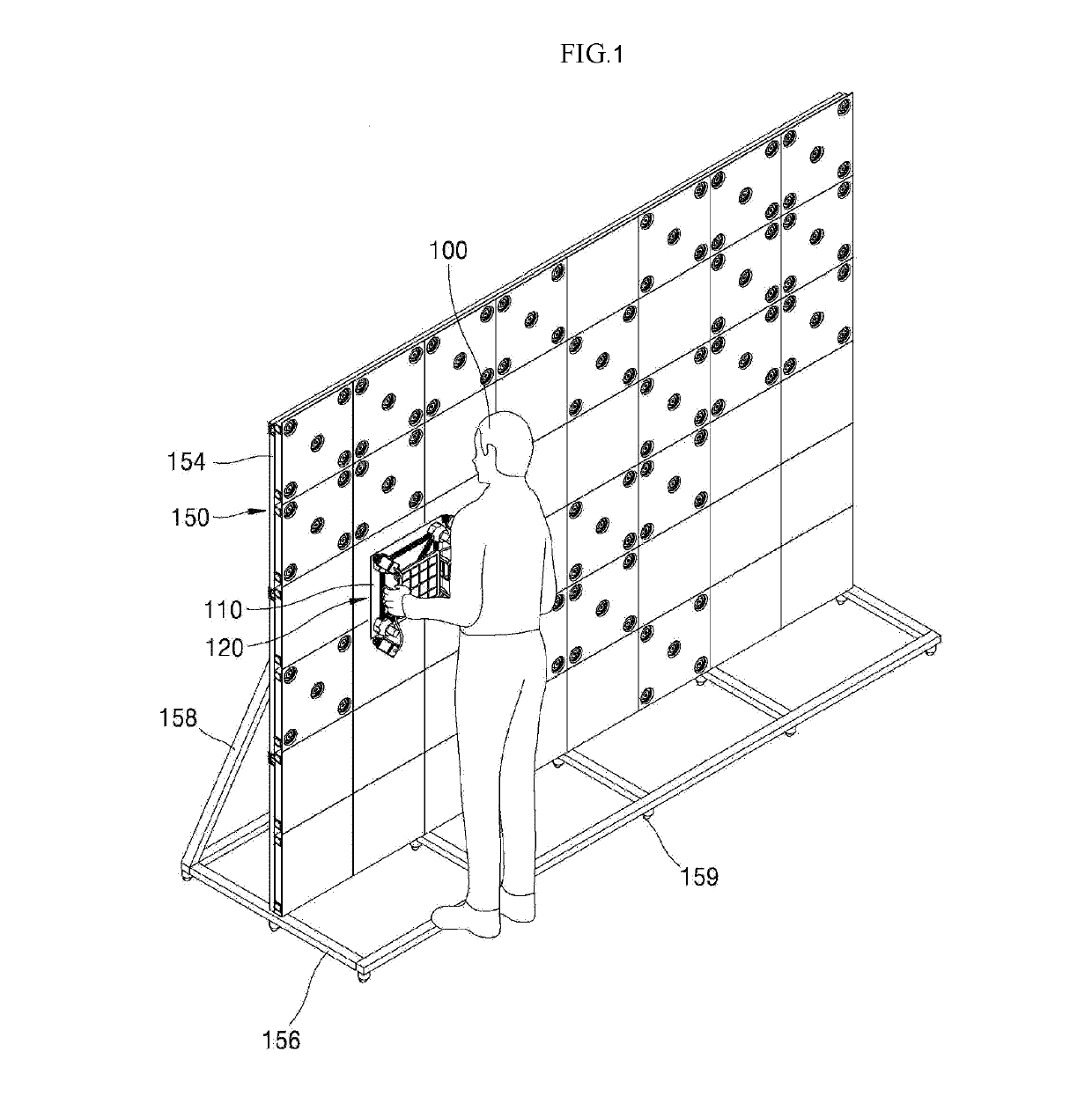
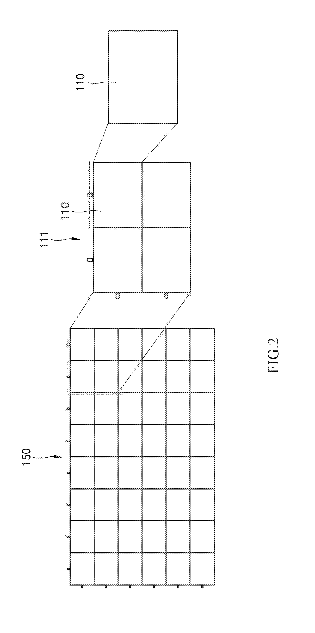
[0102]FIG. 6 is a view illustrating the structure of a tiled display device 150 in accordance with the present disclosure. Since the tiled display device 150 is the same as that shown in FIG. 1, only a coupling structure in which the display panel 110 and the plate 154 of the tiled display device 150 are coupled with each other is specifically shown in the drawing.

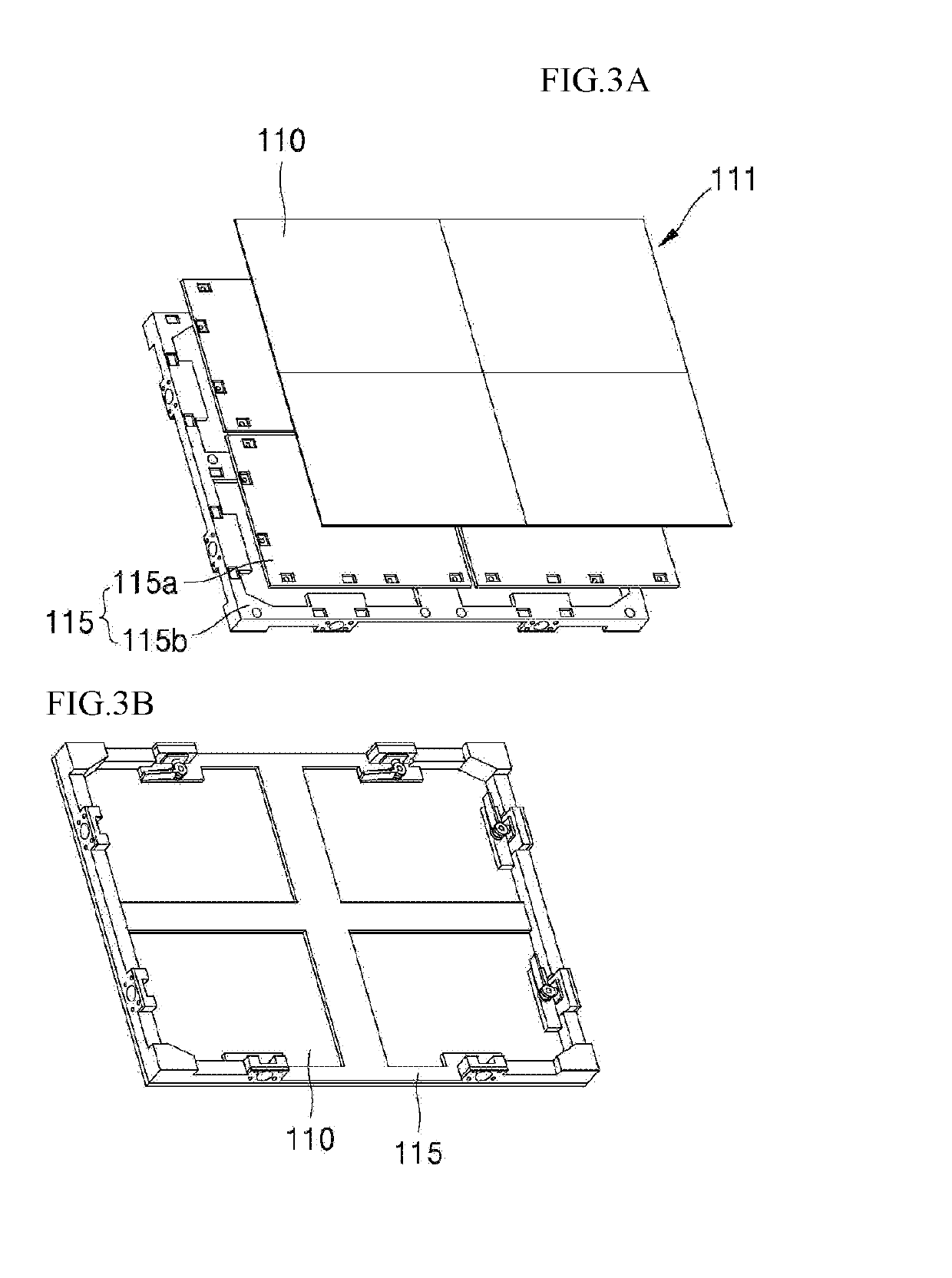
[0103]As shown in FIG. 6, a first coupling unit 160 is disposed around each corners on the rear side of the display panel 110, and a second coupling unit 180 corresponding to the first coupling unit 160 is disposed on the front side of the plate 154 of the tiled display device 150. In a state in which the tiling apparatus 120 is disposed on the front side of the display panel 110 and attached to the display panel 110, the display panel 110 is assembled to the plate 154.

[0104]In order to show the coupling relationship between the first coupling unit 160 and the second coupling unit 180, the plate 154 is not illustrated in t...

second embodiment

[0144]FIGS. 12a to 12d are views illustrating methods for tiling and de-tiling a display panel to and from the tiled display device by the tiling apparatus 120 in accordance with the present disclosure.

[0145]First, as shown in FIG. 12A, in a state in which the display panel 210 is attached to the first magnet 135 of the tiling apparatus 120, as the display panel 210 is moved toward the plate 254 of the tiled display device, the coupling bars 282 of the second coupling unit 280 are inserted into the body 262 of the first coupling unit 260.

[0146]Then, as shown in FIG. 12B, as the display panel 210 attached to the tiling apparatus 120 is further moved forward toward the plate 254, the coupling protrusions 286 formed on the coupling bars 282 come into contact with the inclined portion 269 of the first coupling unit 260. The inclined portion 269 is inclined by the predetermined angle, and the coupling protrusions 286 are also constructed by triangular shapes which have inclined portions....


PUM


Abstract

A display includes a display panel having elements that allow attachment to a mounting structure therebehind and in alignment with adjacent display panels that collectively form a tiled display screen that has multiple display panels connected to each other with effectively seamless bezels. The elements are configured to allow the display panel to be attached to or detached from the tiled display screen in a particular direction other than a side direction that would only allow for engagement from the sides of the adjacent display panels.

Description

[0001]The present disclosure claims the benefit of Korean Patent Application No. 10-2017-0173359 filed on Dec. 15, 2017, Korean Patent Application No. 10-2017-0173361 filed on Dec. 15, 2017, Korean Patent Application No. 10-2017-0173362 filed on Dec. 15, 2017, and Korean Patent Application No. 10-2017-0173363 filed on Dec. 15, 2017, all of which are hereby incorporated by reference.BACKGROUND1. Technical Field[0002]The present disclosure relates to a tiled display device and a tiling apparatus therefor.2. Related Art[0003]As consumers desire to receive and use more information, the demand for various types of display devices has increased. In order to meet these demands, recently, various display devices such as liquid crystal display (LCD) devices, organic light emitting diode (OLED) displays and micro-LED displays are being developed.[0004]Such display devices have been used for various applications ranging from small-sized electronic devices used in mobile phones to large-sized e...

Claims


Application Information

Patent Timeline
IPC IPC(8): H05K5/02H05K5/00G09F9/302
CPCH05K5/0204H05K5/0017H05K5/0021G09F9/3026G06F3/1446F16B5/0664F16B21/086F16B2200/83
Inventor KIM, HANSEOKYOON, SUNGHWANSHIN, HEEJONGLEE, SEUNGCHUL
Owner LG DISPLAY CO LTD
Learn More