Winding core, method for manufacturing the same, and winding core aggregate

a technology of winding core and aggregate, which is applied in the manufacture of magnetic cores, transformers/inductances, and stator/rotor bodies, etc., can solve the problems of winding core breakage or chipping, and achieve the effect of high yield, reduced possibility of breakage or chipping, and efficient shipping or transportation

Active Publication Date: 2019-06-27
MURATA MFG CO LTD
View PDF0 Cites 0 Cited by
  • Summary
  • Abstract
  • Description
  • Claims
  • Application Information

AI Technical Summary

Benefits of technology

[0038]According to preferred embodiments of the present disclosure, a winding core aggregate includes the above winding cores and a carrier sheet that adhesively holds the winding cores near the at least one first terminal electrode and the at least one second terminal electrode with the winding cores arranged in an x-direction and a y-direction that are perpendicular to each other. The winding core aggregate corresponds to an intermediate product that is obtained right after the flattening process is performed to divide the mother substrate in the above method for manufacturing the winding cores. The winding core aggregate can be shipped as the winding cores as products, or can be transported during manufacturing processes. According to preferred embodiments of the present disclosure, the winding core aggregate enables the winding cores that are unlikely to break and chip to be efficiently shipped or transported.
[0039]According to preferred embodiments of the present disclosure, in the manufacturing method, a required form of each winding core is prepared on the mother substrate before the mother substrate is finally divided, and the mother substrate is divided by performing the flattening process on the second main surface of the mother substrate until the second main surface reaches the x-direction division grooves and the y-direction division grooves. This enables a possibility of a break or a chip to be decreased. Accordingly, a very small winding core whose dimension in the longitudinal direction is less than, for example, 1 mm can be manufactured in high yield.

Problems solved by technology

However, it can be thought that winding cores break or chip due to a lack of strength when the winding cores are separated from each other with a dicing machine in the case where the technique disclosed in Japanese Unexamined Patent Application Publication No. 2004-63769 or Japanese Unexamined Patent Application Publication No. 2003-243226 is used to obtain a winding electronic component that has a decreased size, such as a very small winding electronic component whose dimension in the longitudinal direction is less than 1 mm, for example, flat dimension is about 0.4 mm×0.2 mm or 0.2 mm×0.1 mm.

Method used


Image

  • Winding core, method for manufacturing the same, and winding core aggregate
  • Winding core, method for manufacturing the same, and winding core aggregate
  • Winding core, method for manufacturing the same, and winding core aggregate

Examples


first embodiment

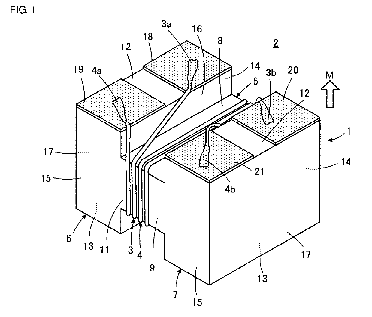
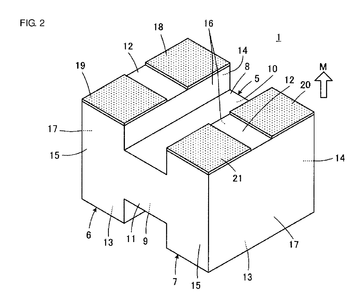
[0069]Referring to FIG. 1 and FIG. 2, a winding-wire-attached electronic component 2 that includes a winding core 1 according to a first embodiment of the disclosure will be described. In FIG. 1 and FIG. 2, the winding-wire-attached electronic component 2 or the winding core 1 is illustrated with a surface that is to be directed to a mounting substrate side M facing upward. The winding-wire-attached electronic component 2 illustrated forms, for example, a common-mode choke coil.

[0070]The winding core 1 that is included in the winding-wire-attached electronic component 2 includes a core portion 5 around which winding wires 3 and 4 are wound. Parts of the winding wires 3 and 4 are omitted in FIG. 1. The core portion 5 is located at a central portion in the longitudinal direction of the winding core 1. The winding core 1 includes first and second flanges 6 and 7 that are respectively connected to first and second end portions of the core portion 5 that are opposite each other in the lo...

second embodiment

[0107]Referring to FIG. 10 to FIG. 15, a winding core 1a according to a second embodiment of the disclosure and a method for manufacturing the winding cores 1a will be described. In FIG. 10 to FIG. 15 and FIG. 16 to FIG. 28, components corresponding to the components illustrated in FIG. 1 to FIG. 9 are designated by like reference numbers, and a duplicated description is omitted.

[0108]FIG. 10 illustrates the winding core 1a with a surface that is to be directed to the mounting substrate side M facing upward. The winding core 1a is used to form, for example, a common-mode choke coil as in the winding core 1.

[0109]The winding core 1a is characterized in that the positions of the first and second core portion side surfaces 10 and 11 are lower than those of the first and second flange side surfaces 14 and 15 unlike the winding core 1, in other words, the first and second core portion side surfaces 10 and 11 are nearer than the first and second flange side surfaces 14 and 15 to the cente...

third embodiment

[0116]FIG. 16 illustrates a winding core 1b according to a third embodiment of the disclosure with a surface that is to be directed to the mounting substrate side M facing upward. The winding core 1b is used to form, for example, a common-mode choke coil as in the winding cores 1 and 1a.

[0117]The winding core 1b is characterized in that the core portion upper surface 9 is flush with each flange upper surface 13 unlike the winding core 1a according to the second embodiment. The winding core 1b can be obtained in the same manner as the method for manufacturing the winding cores 1a according to the second embodiment except that the process of forming the upper surface exposure grooves 33 illustrated in FIG. 8 according to the first embodiment is omitted.


PUM

PropertyMeasurementUnit
sizeaaaaaaaaaa
sizeaaaaaaaaaa
sizeaaaaaaaaaa

Abstract

A mother substrate that enables winding cores to be obtained in a manner in which the mother substrate is divided along x-direction division lines and y-direction division lines is prepared. Subsequently, x-direction division grooves are formed along the x-direction division lines on a first main surface of the mother substrate, y-direction division grooves are formed along the y-direction division lines on the first main surface, and shallow bottom surface exposure grooves, for exposing surfaces that are to be core portion bottom surfaces, are formed on the first main surface. The mother substrate is divided by performing a flattening process on a second main surface of the mother substrate that is opposite the first main surface until the second main surface reaches the x-direction division grooves and the y-direction division grooves to obtain the winding cores that are separated from each other.

Description

CROSS-REFERENCE TO RELATED APPLICATION[0001]This application claims benefit of priority to Japanese Patent Application No. 2017-249004, filed Dec. 26, 2017, the entire content of which is incorporated herein by reference.BACKGROUNDTechnical Field[0002]The disclosure relates to a winding core, a method for manufacturing the winding core, and a winding core aggregate and particularly, to a winding core that is used for a very small winding electronic component whose dimension in the longitudinal direction is less than, for example, 1 mm, a method for manufacturing the winding core, and a winding core aggregate that can be shipped as the winding cores.Background Art[0003]Techniques that are related to the disclosure are disclosed in, for example, Japanese Unexamined Patent Application Publication No. 2004-63769 and Japanese Unexamined Patent Application Publication No. 2003-243226. Japanese Unexamined Patent Application Publication No. 2004-63769 discloses that winding cores that are s...

Claims


Application Information

Patent Timeline
Patent Type & Authority Applications(United States)
IPC IPC(8): H02K15/04H02K15/02
CPCH02K15/0428H02K15/026H02K15/0435H01F41/0206H01F27/24H01F17/045H01F17/03H01F41/0246H01F27/292H01F41/34Y10T29/49792Y10T29/49609Y10T29/49155Y10T29/49073Y10T29/49798Y10T29/4902H01L2224/98H01L24/94H01L21/02013H01F27/26H01L24/97H01F27/266
Inventor YAMAUCHI, EIJI
Owner MURATA MFG CO LTD
Why Eureka
Try Eureka