Rotary Electric Machine and Manufacturing Method for Rotary Electric Machine
a technology of rotary electric machines and manufacturing methods, applied in the direction of applying/manufacturing slot closures, dynamo-electric machines, electrical apparatus, etc., can solve the problems of increasing stray load loss, reducing power factor or torque characteristic, and a relatively high proportion of total loss, so as to achieve low loss and high motor efficiency
- Summary
- Abstract
- Description
- Claims
- Application Information
AI Technical Summary
Benefits of technology
Problems solved by technology
Method used
Image

Examples
example 1
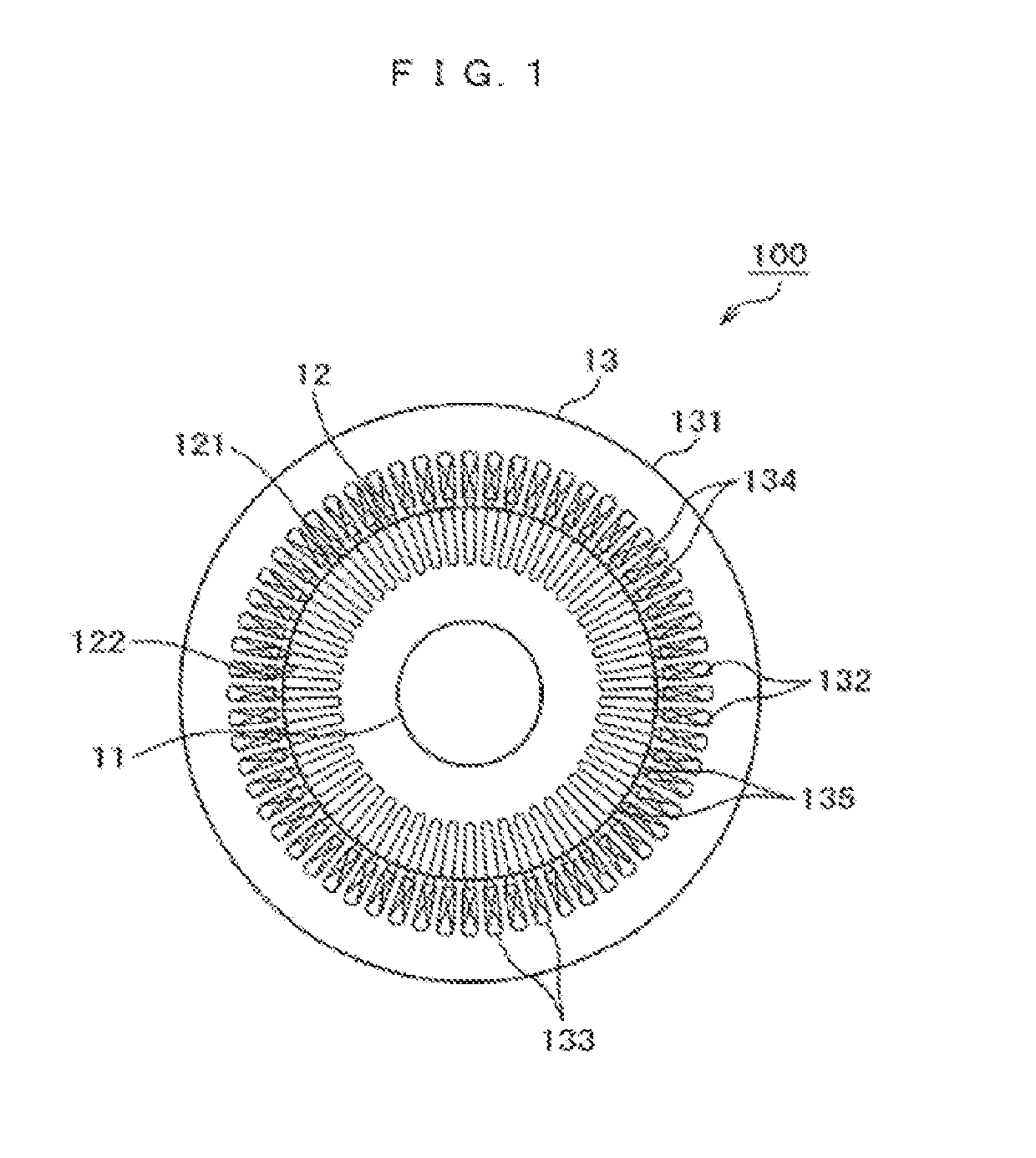
[0034]Hereinafter, Example 1 will be described with reference to FIGS. 1 to 13. As illustrated in FIGS. 1 and 2, a rotary electric machine 100 includes a rotor 12 secured to a rotary shaft (hereinafter, also referred to as a shaft) 11 and a stator 13 installed on an outer side of the rotor 12.
[0035]The rotor 12 includes a rotor core 121, which is a stacked core in which electromagnetic steel sheets punched into a predetermined shape are stacked, and a secondary conductor 122 inserted into a slot of the rotor core 121. The rotor core 121 is secured to a rotary shaft 11, and the rotor 12 is provided to be also rotatable along with rotation of the rotary shaft 11.
[0036]The stator 13 includes a stator core 131, which is a stacked core in which soft magnetic thin plates such as electromagnetic steel sheets punched into a predetermined shape are stacked, and a coil 133 inserted into a slot 132 of the stator core 131. The stator core 131 is arranged opposing a circumferential surface of th...
example 2
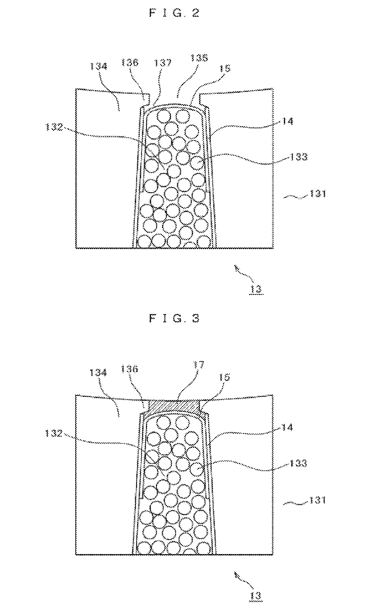
[0078]Hereinafter, a manufacturing method for the rotary electric machine according to Example 2 will be described with reference to FIG. 14. Example 2 is an embodiment in which the mixed substance of the soft magnetic powder and the resin material is solidified in advance so as to become the mixture 17 having stiffness and, then, is mounted in the slot opening 135. Incidentally, the rotary electric machine that is applied in Example 2 has the same configuration as that of the rotary electric machine 100 that is applied in Example 1, except that the slot liner has a different shape and is installed in a different manner.
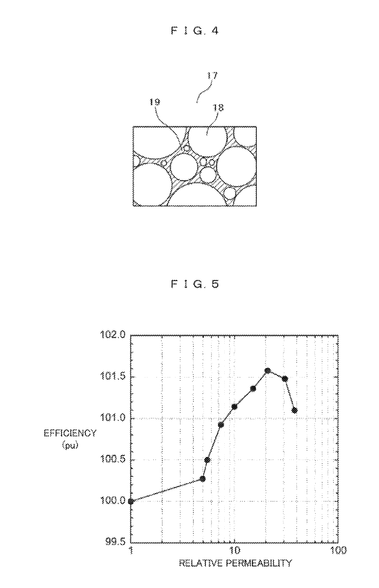
[0079]First, after the soft magnetic powder and the resin material are mixed, and the mixed substance thereof is molded into a fittable shape into the slot opening 135, the resin material contained in the mixed substance is solidified such that the mixture 17 is formed. Subsequently, while the coil 133 is inserted into the slot 132 and is pushed toward a bottom porti...
example 3
[0096]FIG. 15 is an enlarged view illustrating the vicinity of the slot opening of the stator core.
[0097]The slot liner 14 which is an insulator, the coil 133, and the slot liner (or a slice) 15 which is an insulator, are inserted from the outer circumferential side and housed in a housing portion 139 of the slot 132 of the stator core 131. The slot liner 14 on the outer circumferential side insulates a space between the coil 133 and the teeth 134. In addition, the slot liner 15 on the inner circumferential side plays a role of insulation and another role of preventing the coil 133 from projecting from the end portion of the slot opening 135 toward the rotor core. For example, the coil 133 is a coil obtained by winding a conductor like enamel-coated copper wire around the teeth 134.
[0098]Regarding a shape of the slot 132 of the stator core 131 that is provided with the slot opening 135 along an inner diameter of the stator core, the large rotary electric machine mainly uses a comple...
PUM
 Abstract
Description
Claims
Application Information
 - R&D
- Intellectual Property
- Life Sciences
- Materials
- Tech Scout
- Unparalleled Data Quality
- Higher Quality Content
- 60% Fewer Hallucinations
Browse by: Latest US Patents, China's latest patents, Technical Efficacy Thesaurus, Application Domain, Technology Topic, Popular Technical Reports.
© 2025 PatSnap. All rights reserved.Legal|Privacy policy|Modern Slavery Act Transparency Statement|Sitemap|About US| Contact US: help@patsnap.com