Blood pressure status measuring apparatus

a technology of blood pressure and measuring apparatus, which is applied in the field of blood pressure status measuring apparatus, can solve the problems of not considering accurately measuring circulatory dynamics including the blood pressure status of arterioles or capillaries, arterial hypertension will lead to cerebral bleed, etc., and achieves the effect of improving the accuracy of blood pressure estimation and the like, and measuring more simply and more accurately

Pending Publication Date: 2019-07-11
MURATA MFG CO LTD
View PDF1 Cites 7 Cited by
  • Summary
  • Abstract
  • Description
  • Claims
  • Application Information

AI Technical Summary

Benefits of technology

[0007]The present invention has been made to solve the above problems, and an object of the present invention is to provide a blood pressure status measuring apparatus that is capable of measuring circulatory dynamics including the blood pressure status of arterioles or capillaries more simply and more accurately.

Problems solved by technology

It has been widely known that there is a high risk that arterial hypertension will lead to cerebral bleed and the like.
In actuality, however, it is often the case that bleeding occurs in arterioles or capillaries that are narrower than arteries.
However, in the technique of Patent Document 1, accurately measuring circulatory dynamics including the blood pressure status of arterioles or capillaries is not considered.

Method used


Image

  • Blood pressure status measuring apparatus
  • Blood pressure status measuring apparatus
  • Blood pressure status measuring apparatus

Examples


Embodiment Construction

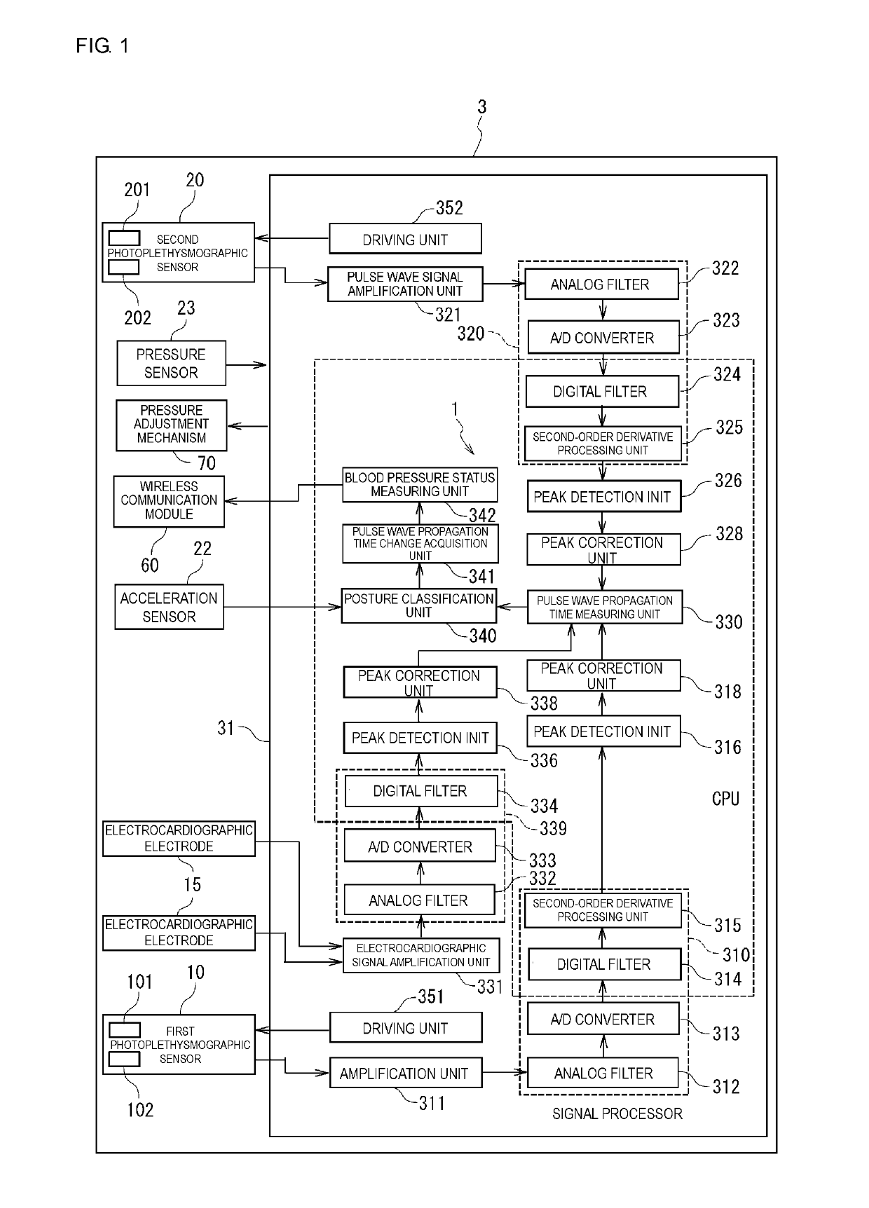
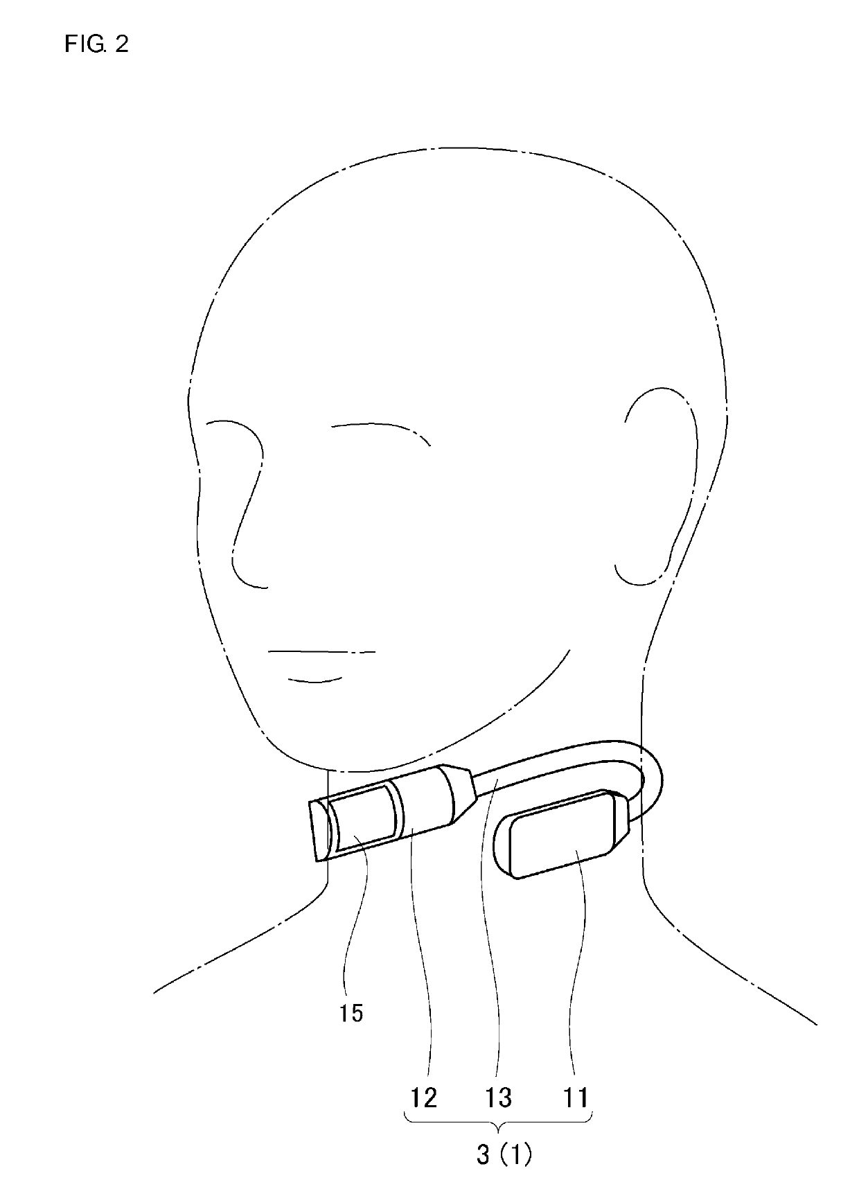
[0048]Hereinafter, preferred embodiments of the present invention will be described in detail below with reference to drawings. In the drawings, the same or corresponding parts will be referred to with the same signs. Furthermore, the same signs will be assigned to the same elements, and redundant explanation will be omitted.

[0049]First, a configuration of a blood pressure status measuring apparatus 3 according to an embodiment will be explained with reference to FIGS. 1 and 2. The blood pressure status measuring apparatus 3 includes a pulse wave propagation time measuring device 1. FIG. 1 is a block diagram illustrating a configuration of the blood pressure status measuring apparatus 3 including the pulse wave propagation time measuring device 1. FIG. 2 is a perspective view illustrating the external appearance of the blood pressure status measuring apparatus 3 of a neck band type including the pulse wave propagation time measuring device 1.

[0050]The blood pressure status measuring...


PUM


Abstract

A blood pressure status measuring apparatus includes a first photoplethysmographic sensor that includes a light emitting element) outputting near-infrared light and acquires a photoplethysmographic signal of a carotid artery, a second photoplethysmographic sensor that includes a light emitting element outputting blue to yellow-green light and acquires a photoplethysmographic signal of an arteriole or a capillary near the carotid artery, a pulse wave propagation time measuring unit that acquires a pulse wave propagation time on the basis of the photoplethysmographic signal of the carotid artery and the photoplethysmographic signal of the arteriole or the capillary near the carotid artery, a pulse wave propagation time change acquisition unit that acquires a temporal change of the pulse wave propagation time after measurement is started, and a blood pressure status measuring unit that measures circulatory dynamics including a blood pressure status on the basis of the temporal change of the pulse wave propagation time after measurement is started.

Description

CROSS REFERENCE TO RELATED APPLICATIONS[0001]The present application is a continuation of International application No. PCT / JP2017 / 028703, filed Aug. 8, 2017, which claims priority to Japanese Patent Application No. 2016-157257, filed Aug. 10, 2016, the entire contents of each of which are incorporated herein by reference.TECHNICAL FIELD[0002]The present invention relates to a blood pressure status measuring apparatus, and particularly, to a blood pressure status measuring apparatus using a pulse wave propagation time.BACKGROUND OF THE INVENTION[0003]In recent years, for example, as an index for evaluation of the degree of arteriosclerosis, estimation of the life span of blood vessels, and the like, a pulse wave propagation time, which is a time in which a pulse wave propagates inside an artery of a living body (for example, a time up to arrival of a pulse wave from an R wave of an electrocardiogram), has been used. The pulse wave propagation time reflects a change in blood pressure...

Claims


Application Information

Patent Timeline
Patent Type & Authority Applications(United States)
IPC IPC(8): A61B5/021A61B5/024A61B5/0245A61B5/0456A61B7/02A61B5/00A61B5/352
CPCA61B5/02125A61B5/02416A61B5/0245A61B5/0456A61B7/02A61B5/6822A61B2562/0247A61B5/6843A61B5/7264A61B5/1116A61B2562/0219A61B2562/0215A61B7/00A61B5/352A61B5/349
Inventor SHIMUTA, TORU
Owner MURATA MFG CO LTD
Why Eureka
Try Eureka