Vacuum insulation glass panel assembly manufacturing method and apparatus

a technology of vacuum insulation glass and assembly, which is applied in the direction of layered products, mechanical equipment, chemistry apparatus and processes, etc., can solve the problems of high cost, difficult to handle the vacuum insulation glass panel assembly, and most of the energy loss generated during heating and cooling of buildings, etc., and achieve the effect of low cost and continuous manufacturing of vacuum plate glass assemblies

Active Publication Date: 2019-07-11
PARK JE IL
View PDF0 Cites 2 Cited by
  • Summary
  • Abstract
  • Description
  • Claims
  • Application Information

AI Technical Summary

Benefits of technology

[0025]According to the vacuum insulation glass panel assembly manufacturing method of the present invention, it is possible to manufacture vacuum insulation glass panel assemblies of various sizes in one manufacturing facility. Furthermore, according to the manufacturing method of the present invention, it is possible to continuously manufacture vacuum plate glass assemblies by sealing the exhaust port in the vacuum oven using the lid member closing device mounted with the lid member. In addition, according to the manufacturing method of the present invention, the air exhaust step and the exhaust port sealing step for the vacuum insulation glass panel assembly are performed in different chambers. Therefore, the glass panel assemblies can be mass-produced at a low cost while continuously feeding the glass panel assemblies through the conveyor.

Problems solved by technology

In particular, most of the energy loss that occurs during heating and cooling of buildings is generated through windows.
In the case of manufacturing a vacuum insulation glass panel assembly using an exhaust pipe, there is a problem that a defect is likely to occur due to the damage of the exhaust pipe during the manufacture of the vacuum insulation glass panel assembly and further that it is difficult to handle the vacuum insulation glass panel assembly because the exhaust pipe remains in a protruding state.
Therefore, sealing failure is likely to occur because it is difficult to accurately position the sealing apparatus in the exhaust port of each of the glass panel assemblies having various sizes.
Furthermore, the productivity is low because it is difficult to realize automation.
In particular, the invention disclosed in Patent Document 1 has a problem in that sealing failure due to thermal deformation occurs because only the lid member is locally heated and brought into contact with the periphery of the exhaust port of the glass panel assembly having a low temperature.
However, Patent Document 3 does not specifically suggest or disclose a method or apparatus for supplying a lid member to above an exhaust port of a glass panel assembly disposed inside a vacuum oven.
This makes it difficult to change the position of a mechanism for pressing the lid member provided inside the vacuum oven.
Second, the support member such as a spring or the like used for keeping the lid member above the exhaust port of the glass panel remains inside the glass panel assembly after sealing.
This may cause noise or damage to the glass panel assembly during movement or storage of the glass panel assembly.
Third, in the process of manufacturing the glass panel assembly, the lid member is dropped or the position of the lid member is changed during the movement thereof.
Thus the lid member fails to accurately seal the exhaust port of the glass panel and sealing failure may occur.
Fourth, it is difficult to automate the manufacturing process due to the complexity in the installation of the support member for supporting the lid member and the lid member.

Method used


Image

  • Vacuum insulation glass panel assembly manufacturing method and apparatus
  • Vacuum insulation glass panel assembly manufacturing method and apparatus
  • Vacuum insulation glass panel assembly manufacturing method and apparatus

Examples


Embodiment Construction

[0036]Preferred embodiments of the present invention will now be described in detail with reference to the accompanying drawings.

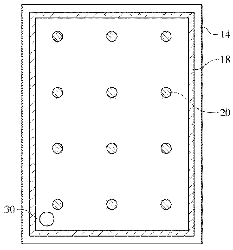
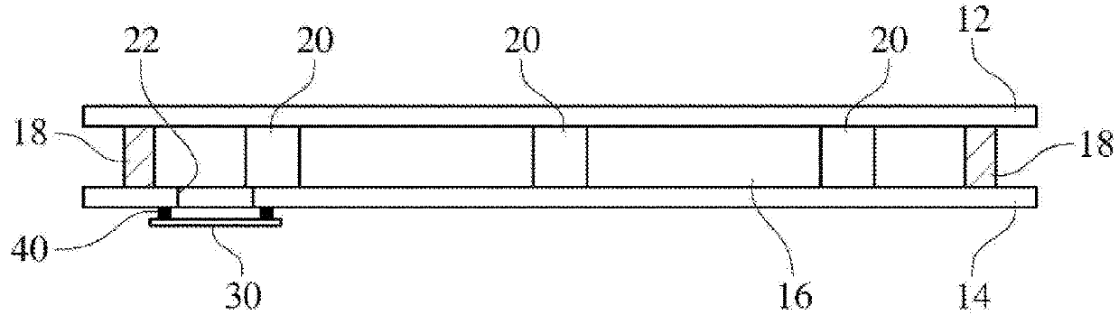
[0037]Referring to FIGS. 1 and 2, a vacuum insulation glass panel assembly 10 manufactured using the method and apparatus of the present invention will be described. The vacuum insulation glass panel assembly 10 includes an upper glass panel 12, a lower glass panel 14 and a solder glass 18 applied to an edge between the upper glass panel 12 and the lower glass panel 14 facing each other and configured to define a depressurized vacuum space. A solder glass having a high melting point is used as the solder glass (frit) for sealing the edge of the glass panel assembly. It is preferable that a solder glass melted at a temperature in the range of 380 to 460 degrees C. is used as the solder glass 18 having a high melting point. The upper glass panel 12 and the lower glass panel 14 are spaced apart from each other by a predetermined distance to define a vacuum sp...


PUM

PropertyMeasurementUnit
pressureaaaaaaaaaa
melting pointaaaaaaaaaa
temperatureaaaaaaaaaa

Abstract

Provided is a vacuum insulation glass panel assembly manufacturing method and apparatus. The vacuum insulation glass panel assembly manufacturing method includes an edge sealing step of sealing an edge of a glass panel assembly of glass panels spaced apart at a predetermined interval, and an exhaust port sealing step of causing a lid member to seal an exhaust port of the glass panel assembly formed so as to communicate with a space between the glass panels whose edges are sealed. A glass solder having a high melting point is used in the edge sealing step, and a glass solder having a low melting point is used in the exhaust port sealing step. A specially designed lid member closing device is used for exhaust port sealing.

Description

TECHNICAL FIELD[0001]The present invention relates to a vacuum insulation glass panel assembly manufacturing method and apparatus.BACKGROUND ART[0002]Techniques are being developed to reduce the energy loss that occurs during heating and cooling of buildings. In particular, most of the energy loss that occurs during heating and cooling of buildings is generated through windows. A vacuum insulation glass panel assembly has been developed to prevent energy loss through glass windows.[0003]As a conventional method for manufacturing a vacuum insulation glass panel assembly, there is known a technique of connecting an exhaust pipe to an exhaust port of a glass panel assembly, evacuating a sealed space formed between a pair of glass panels through an exhaust pipe, and sealing the exhaust pipe. In the case of manufacturing a vacuum insulation glass panel assembly using an exhaust pipe, there is a problem that a defect is likely to occur due to the damage of the exhaust pipe during the manu...

Claims


Application Information

Patent Timeline
Patent Type & Authority Applications(United States)
IPC IPC(8): C03C27/10B32B17/10B32B7/12E06B3/677
CPCC03C27/10B32B17/10036B32B7/12E06B3/6775F16L59/065E06B3/6612B32B17/10C03C27/06E06B3/6733Y02A30/249Y02B80/22B32B17/10045B32B2315/08E06B3/67334E06B3/67365E06B3/67386E06B3/6736
Inventor PARK, JE IL
Owner PARK JE IL
Why Eureka
Try Eureka