System and method for active injection into fluid streams

Active Publication Date: 2019-07-11
TUSKEGEE UNIVERSITY
View PDF0 Cites 0 Cited by
  • Summary
  • Abstract
  • Description
  • Claims
  • Application Information

AI Technical Summary

Benefits of technology

The patent describes a nozzle block that includes micronozzles that direct fuel towards a compressible vortex generated by a pulsed air jet. The nozzle block is designed to improve mixing of fuel and air in supersonic jet engines, such as scramjet engines, to enhance combustion efficiency. The compressible vortex formed by the pulsed air jet helps to capture and entrain the fuel, which is then driven into a central portion of a cross-directional flow stream. This mixing process can contribute to better engine performance.

Problems solved by technology

In certain power generation scenarios, the time the fuel and oxidizer are in the combustion chamber may be short, often only milliseconds.
In certain embodiments, injection nozzles utilized for sub-sonic jet engines or power generation turbines may be unsuitable for the fast mixing occurring at supersonic speeds.

Method used


Image

  • System and method for active injection into fluid streams
  • System and method for active injection into fluid streams
  • System and method for active injection into fluid streams

Examples


Embodiment Construction

[0027]The foregoing aspects, features, and advantages of the present disclosure will be further appreciated when considered with reference to the following description of embodiments and accompanying drawings. In describing the embodiments of the disclosure illustrated in the appended drawings, specific terminology will be used for the sake of clarity. However, the disclosure is not intended to be limited to the specific terms used, and it is to be understood that each specific term includes equivalents that operate in a similar manner to accomplish a similar purpose.

[0028]When introducing elements of various embodiments of the present disclosure, the articles “a”, “an”, “the”, and “said” are intended to mean that there are one or more of the elements. The terms “comprising”, “including”, and “having” are intended to be inclusive and mean that there may be additional elements other than the listed elements. Any examples of operating parameters and / or environmental conditions are not...


PUM


Abstract

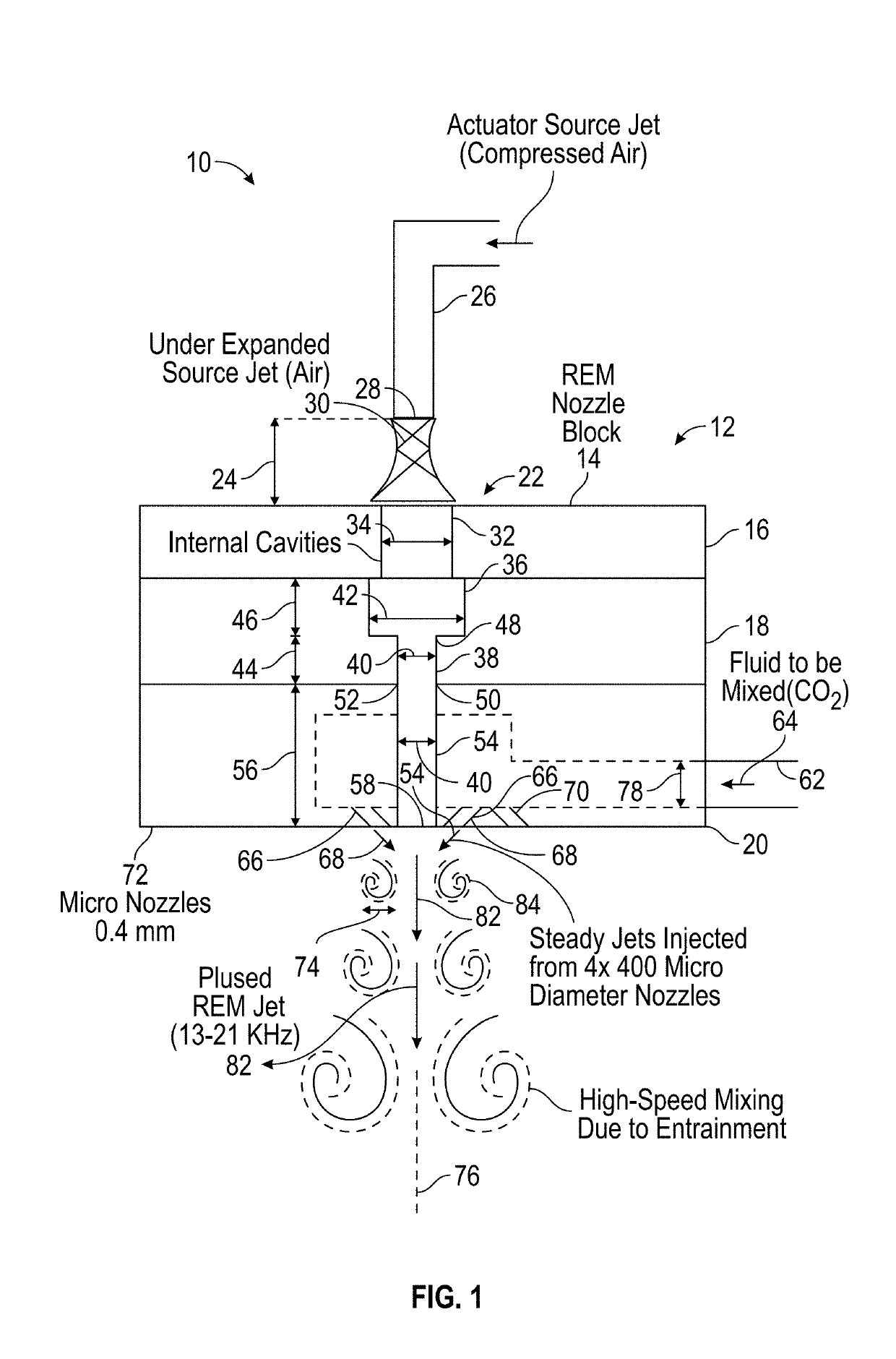
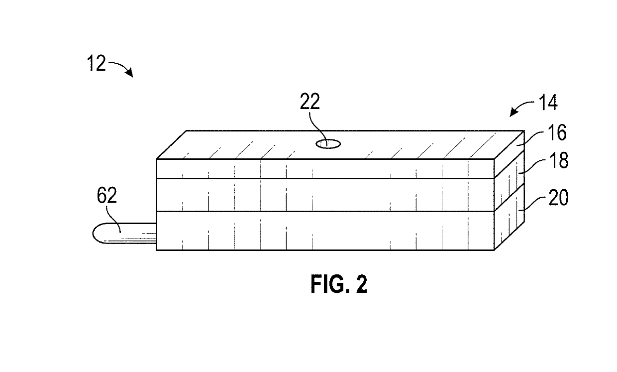
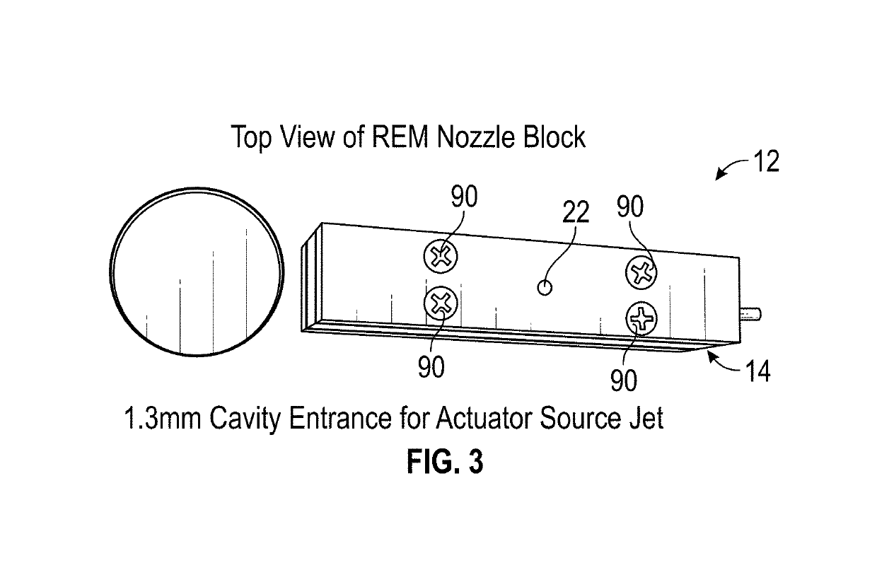
Embodiments of the present disclosure include an injection system. The injection system includes a Resonance Enhanced Microjet (REM) nozzle. The REM nozzles includes a REM nozzle block, the REM nozzle block having an inlet formed in a top and an outlet formed in a bottom, the inlet and outlet being fluid coupled together. The REM nozzle also includes one or more micronozzles positioned about the outlet, the one or more micronozzles having an outlet and being positioned at an angle relative to the bottom. Additionally, the REM nozzle includes an inlet conduit coupled to the REM nozzle block, the inlet conduit being fluidly coupled to the one or more micronozzles. The injection system also includes a source arranged proximate the top, the source directing a source jet of fluid into the inlet. The injection system includes a fuel supply fluidly coupled to the inlet conduit. Such a system can inject a fuel entrained in an oxidizer pulsing at very high-frequency. These pulsed fuel-oxidizer streams can be injected to a high-velocity fluid stream which allows better mixing of fuel and oxidizer at high speed.

Description

PRIORITY APPLICATION[0001]This application claims priority to U.S. provisional application 62 / 611,349 filed on Dec. 28, 2017, which application is herein incorporated by reference in its entirety.GOVERNMENT LICENSE RIGHTS[0002]This invention was made with government support under Grant 1504865 awarded by National Science Foundation. The government has certain rights in the invention.BACKGROUND1. Field of the Invention[0003]The present disclosure relates to active fluid injection systems. More particularly, the present disclosure relates to systems and methods for injecting fluids actively into high-speed flow streams for mixing.2. Description of Related Art[0004]High-speed fluid mixing may be utilized in power generation, such as jet engines. In applications, an oxidizer is accelerated at a fast rate, often greater than Mach 1 (i.e., a speed greater than the speed of sound), toward a combustion chamber. In the combustion chamber, a fuel may be injected into the flow stream comprisin...

Claims


Application Information

Patent Timeline
IPC IPC(8): F02K7/02
CPCF02K7/02F02K9/52B01F25/314
Inventor SOLOMON, JOHN
Owner TUSKEGEE UNIVERSITY
Why Eureka
Try Eureka