Dry additive and fluid mixing system, assembly and method

a technology of additives and fluids, applied in the direction of mixing, transportation and packaging, rotary stirring mixers, etc., can solve the problems of limited transportation infrastructure, logistical challenges, and difficulty in on-site mixing

Active Publication Date: 2019-07-18
MGB OILFIELD SOLUTIONS LLC
View PDF0 Cites 129 Cited by
  • Summary
  • Abstract
  • Description
  • Claims
  • Application Information

AI Technical Summary

Problems solved by technology

However, on-site mixing is not without its challenges.
For example, many on-site mixing locations are remote and present logistical challenges such as long travel distances, limited transportation infrastructure, hostile climates and primitive or crude chemical storage conditions for dry additives and / or liquids.
However, transportation costs for transporting batch mixtures to certain locations are high.
Batch mixing has also been attempted on-site but relies heavily on the storage of dry products on location and often times there is no space available for such material storage.
In addition, batch mixing can often be wasteful.
Also, during transit and depending on the chemistry of the mixture, a batch mixture may be subject to chemical reactions and temperature degradation thereby damaging the mixture before reaching its destination.
However, in many industries, especially in the extraction of oil and gas, and specifically in hydraulic fracturing operations, the use of liquid chemicals on-site in continuous mixing operations is also cost prohibitive.
There have been attempts to create continuous mixing packages that are field transportable but such have several shortcoming including: (1) the large size of mixing units currently available (length, width, depth), (2) the substantial weight of units currently available, (3) the complexity of current designs, which can make maintenance and operating such units challenging and adds costs depending on the location of operation, (4) component failures leading to the asset not being available to perform operations as necessary, (5) the inability to remotely operate the mixing units, (6) the lack of quality and control of the mixing process necessary to provide one or more required fluid mixtures and (7) supply chain challenges, e.g., bulk material needs to be transported in large pneumatic trailers to the field.

Method used


Image

  • Dry additive and fluid mixing system, assembly and method
  • Dry additive and fluid mixing system, assembly and method
  • Dry additive and fluid mixing system, assembly and method

Examples


example 1

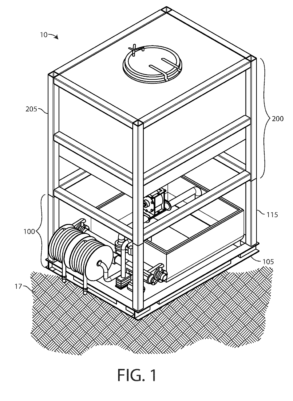
[0145]In a first non-limiting example, a system 10 as shown in FIG. 1 operationally configured for oil and gas extraction operations may be provided having the dimensions as shown in Table 3 below.

TABLE 3(1)First Module 100Framework 105 Width: about 1.93 meters (about 76.0 inches)Framework 105 Length: about 2.54 meters (about 100.0 inches)Height from the bottom of the Framework 105 tothe top of the VerticalMembers 115: about 1.55 meters (about 61.2 feet)(2)Second Module 200Framework 205 Width: about 1.93 meters (about 76.0 inches)Framework 205 Length: about 2.54 meters (about 100.0 inches)Framework 205 Height: about 2.22 meters (about 87.25 inches)(3)Storage Container 206 Volume: about 7.79 cubic meters(about 275.0 cubic feet).

[0146]In still another aspect, the present application is directed to a system for producing fluid mixture compositions, including a first module for providing fluid; and a second module attachable to the first module for providing dry additive to be mixed wit...


PUM

PropertyMeasurementUnit
volumeaaaaaaaaaa
volumeaaaaaaaaaa
sizeaaaaaaaaaa

Abstract

The application is directed to a system and method for mixing fluid and dry material to produce fluid mixture compositions. The system may be provided on a portable platform for transport of the system for use at different locations or the system may be provided as a permanent installation. The system includes a first module for receiving fluid into the system and an optional second module attachable to the first module for providing dry material to be mixed with the fluid received into the system. The fluid mixture compositions produced by the system can be conveyed out from the system to one or more target locations.

Description

CROSS-REFERENCE TO RELATED APPLICATIONS[0001]This application claims benefit of U.S. Provisional Patent Application Ser. No. 62 / 617,164, filed on Jan. 12, 2018, the content of which is hereby incorporated by reference in its entirety.STATEMENT REGARDING FEDERALLY SPONSORED RESEARCH OR DEVELOPMENT[0002]Not applicable.FIELD OF THE INVENTION[0003]The application relates generally to the mixing of dry additives and fluids.BACKGROUND OF THE INVENTION[0004]On-site mixing of dry additives with fluids is a common operation in many industries, including for example, oilfield operations, mining, pulp industry, paper industry, pharmaceutical preparation, food preparation and processing, cosmetics industry, plastics industry, construction and agriculture. However, on-site mixing is not without its challenges. For example, many on-site mixing locations are remote and present logistical challenges such as long travel distances, limited transportation infrastructure, hostile climates and primitive...

Claims


Application Information

Patent Timeline
Patent Type & Authority Applications(United States)
IPC IPC(8): B01F3/12B01F13/00B01F15/02
CPCB01F3/1271B01F13/0032B01F15/0234B01F2003/125B01F2215/0081B01F23/50B01F23/53B01F25/4231B01F25/316B01F25/45B01F25/60B01F33/5024B01F33/5023B01F27/90B01F33/811B01F35/2112B01F35/2135B01F35/2115B01F35/2211B01F23/59B01F33/5013B01F35/7173B01F23/56B01F2101/49
Inventor BISHOP, MARK DANIEL
Owner MGB OILFIELD SOLUTIONS LLC
Why Eureka
Try Eureka