Roller board with one or more user-maneuverable trucks and north-seeking return mechanism

Active Publication Date: 2019-07-18
ROLL INC
View PDF0 Cites 2 Cited by
  • Summary
  • Abstract
  • Description
  • Claims
  • Application Information

AI Technical Summary

Benefits of technology

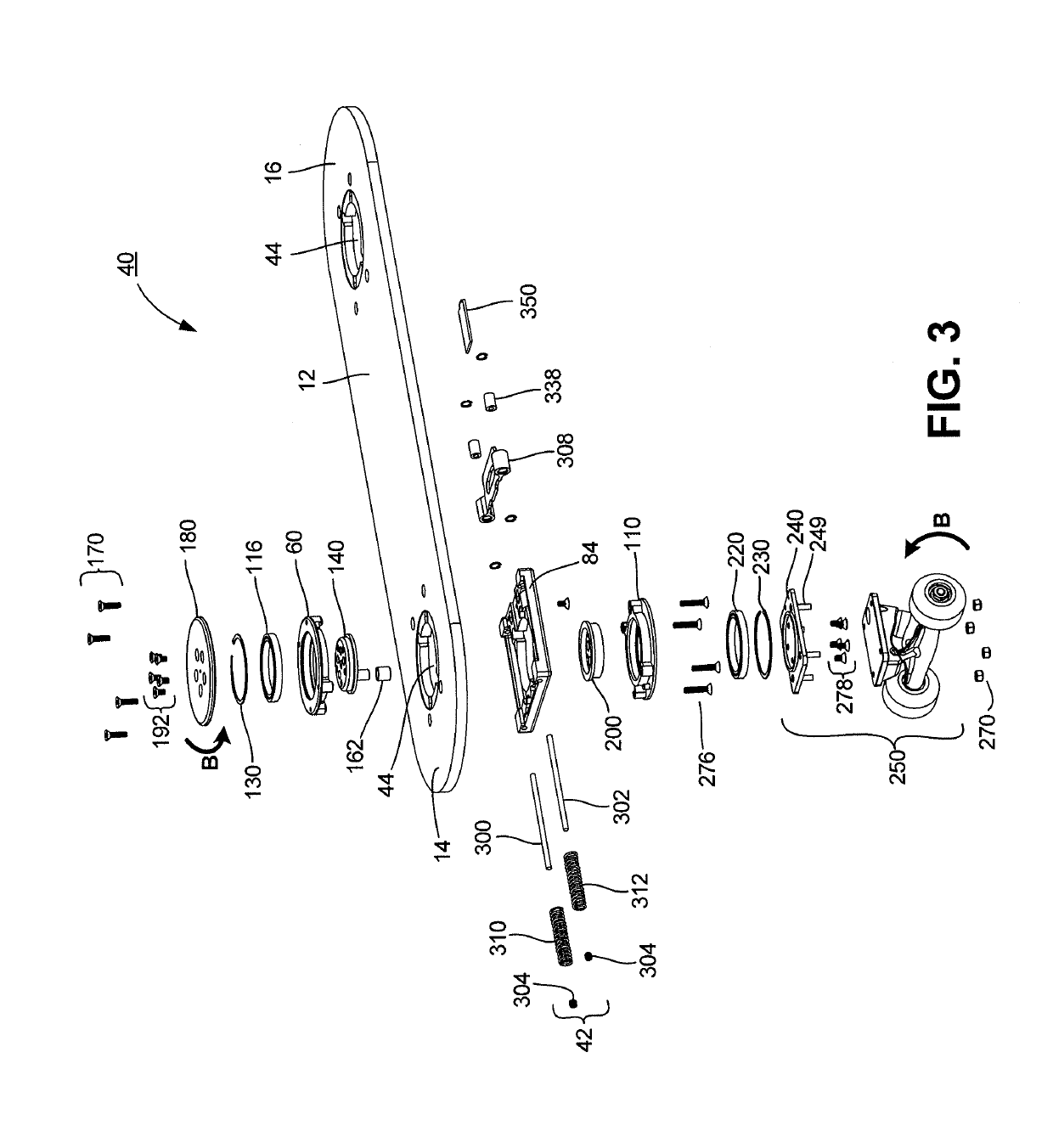
[0029]When the user's foot releases the rotational force from the foot pad, the stored energy in the retracted compression spring will cause the spring to expand to its original length to push against the shoulder of connecting rod to extend the connecting rod outwardly from pivot block and out of the tubular support, counter-rotating the crankshaft in the process to return it to its true-north position. Thus, this north-seeking return mechanism converts the rotational movement of the crankshaft into linear movement of the connecting rod similarly to the north-seeking return mechanism translating the rotational movement of crankshaft into linear movement of Scotch yoke. Moreover, mechanism enables 360 degree rotation and counter rotation of the wheel assembly just like mechanism 42 achieves. The foot pad and wheel assembly can also be turned by the user in a counterclockwise direction with the same effect.
[0030]Still another embodiment of a north-seeking return mechanism comprises a unitary crankshaft having an offset cam lobe. It interacts with a Scotch yoke that is moved along a linear axis within a housing. A piston shaft extends from the Scotch yoke outside the housing. A single compression spring is disposed along the piston shaft between an exterior wall of the housing and a bushing or nut. When the rotation assembly is turned by the user, force is applied to the user interface member, the crankshaft is rotated in the same direction and degree as the user interface member to turn the wheel assembly of the roller board device, and the offset cam lobe of the rotated crankshaft bears against the trailing edge of an open window in the Scotch yoke of the

Problems solved by technology

This action requires balance and coordination by the user and can provide challenges to a beginner or novice rider.
Once content with two-dimensional freestyle tricks such as wheelies, manuals, and pivots, popular skateboard tricks have become more complicated, three-dimensional, aerial maneuvers.
But this device requires more balance and coordination then many users can muster.
While convenient for a user riding along a street or sidewalk for recreation, this steering shaft can interfere with aerial trick maneuvers.
It can also provide a safety hazard to the user.
A compression spring connected between this disc and the bottom of the chassis of the wagon further limits the degree to which the front axle may be turned upon impact with an impediment, and biases the front wheels to their centered position.
However, the limited ability of the compression spring to pull the front axle back to its “true center” position is acceptable, because the user may easily use the handle bar to steer the wagon.
Thus, the skateboard according to Cooney does not provide the kind of maneuverability required for tricks.
However, the user's right foot is positioned above the left foot which can throw off balance.
Moreover, the large circular platform extends from the rear end of the skateboard, which int

Method used


Image

  • Roller board with one or more user-maneuverable trucks and north-seeking return mechanism
  • Roller board with one or more user-maneuverable trucks and north-seeking return mechanism
  • Roller board with one or more user-maneuverable trucks and north-seeking return mechanism

Examples


Example

[0238]The design of this third embodiment 700 of the roller board invention reduces the number of parts and resulting complexity found in the first embodiment 10. The upper bearing housing and lower bearing housing for holding the upper and lower bearings have been eliminated. The piston rod forms part of the Scotch yoke, instead of having to employ two separate piston rods. Unlike the first embodiment for the roller board 10 and much of the prior art, a single compression spring is used instead of two separate compression springs. The housing design for this third embodiment allows the single compression spring 962 to apply its force uniformly across the width of the Scotch yoke that moves within the housing chamber without sideways wobble. Normally, two compression springs would be required to exert force against the left and right portions of the Scotch yoke. Finally, the third embodiment 700 of the roller board design employs a unitary crankshaft with an offset cam lobe instead ...


PUM


Abstract

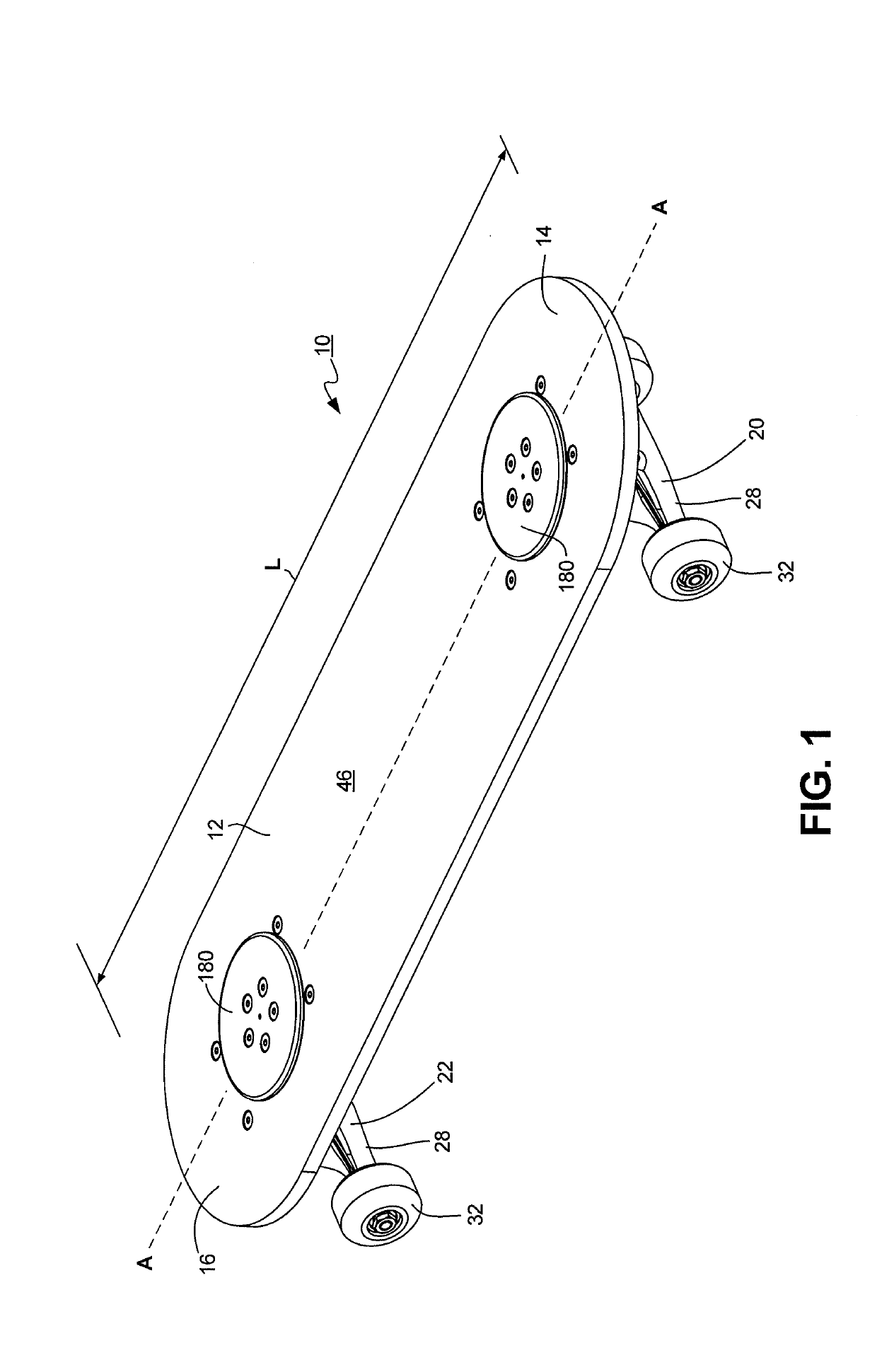
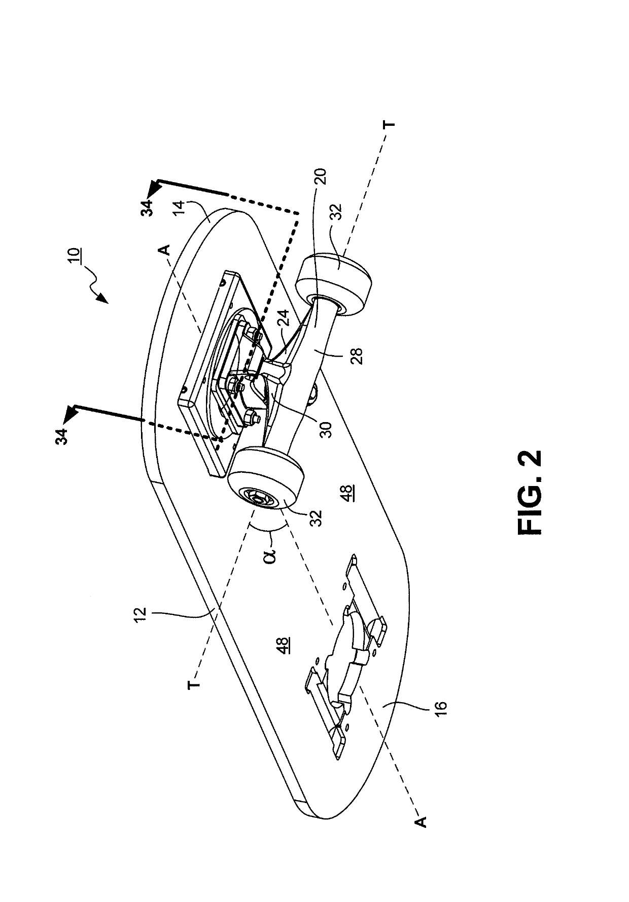
A roller board device like a skateboard or scooter operated by a user with one or more user-maneuverable wheel assemblies that are automatically returned to their “true north” position is provided according to the invention. The roller board device comprises an elongated deck, at least one wheel assembly, a rotation assembly operatively engaging and extending through the opening in the deck, one end of the rotation assembly being connected to the wheel assembly positioned below the deck, the other end of the rotation assembly being connected to a user interface member extending upward beyond the top surface of the deck, and a north-seeking return mechanism secured to the deck containing an engagement member movable along a linear axis within a housing and engaging a spring disposed between the engagement member and an interior wall of the housing, the rotation assembly operatively connected to the engagement member to convert rotational movement of the rotation member into linear movement of the engagement member. When the user applies rotational force to the user engagement member to turn it to the left or right, the rotation assembly and wheel assembly are rotated in the same direction and degree to allow the roller board device to be turned, the rotated rotation assembly interacting with the engagement member of the north-seeking return mechanism to move the engagement member along its linear axis to a retracted position to compress the spring. But, when the user releases the rotational force upon the user interface member, the spring extends from its compressed state to its elongated state to move the engagement member of the north-seeking return mechanism back along the linear axis from its retracted position to its standby position, counter interacting with the rotation assembly to return the wheel assembly of the roller board device to its true north position.

Description

CROSS-REFERENCE TO RELATED APPLICATION[0001]This application is a continuation-in-part of U.S. Ser. No. 15 / 897,943 filed on Feb. 15, 2018, which is a continuation-in-part of U.S. Ser. No. 15 / 433,842 filed on Feb. 15, 2017, both of which are hereby incorporated in their entirety.FIELD OF THE INVENTION[0002]The present invention relates to self-propelled roller boards like skateboards and scooters, and more particularly to a skateboard or scooter with one or more steerable trucks that may be independently maneuvered by the user while riding the skateboard or scooter to steer it in a desired direction, and automatically returned to their standby “true north” position once the user is no longer steering them.BACKGROUND OF THE INVENTION[0003]Skateboarding has become a popular recreation and sport. Derived from the late-1940's surfing scene in California as an activity for when the waves were flat, early skateboards were comparatively primitive devices comprising wooden boxes with roller ...

Claims


Application Information

Patent Timeline
IPC IPC(8): B62K21/10B62K21/24B62K3/00
CPCB62K21/10B62K21/24B62K3/002
Inventor CLOS, DAVEVETTER, WILLIAM CHARLESPONGRATZ, TROY A.
Owner ROLL INC
Why Eureka
Try Eureka