Eureka AIR delivers breakthrough ideas for toughest innovation challenges, trusted by R&D personnel around the world.

Traffic and geography based cognitive disaster recovery

a cognitive disaster recovery and traffic-based technology, applied in the field of data disaster recovery, can solve the problems of high data volume transaction occurring when the system administrator attempts a planned disaster recovery procedure and fails, and the primary site may be gradually failing,

Active Publication Date: 2019-07-18
IBM CORP
View PDF9 Cites 3 Cited by
  • Summary
  • Abstract
  • Description
  • Claims
  • Application Information

AI Technical Summary

Benefits of technology

This patent describes a system that uses machine learning to analyze different system parameters and predict how those parameters would react in an emergency or planned disaster recovery scenario. Based on these predictions, the system can automatically configure appropriate procedures and decisions to facilitate the migration of data and transactions to the backup or target site. This approach helps to minimize disruption and improve the overall resilience of the system.

Problems solved by technology

(a) A disaster event may be triggered by and / or involve critical resource errors and, in such cases, any critical transactions running at the time of a disaster recovery procedure might not be completed.
(b) A critical transaction occurring when the system administrator initiates a planned disaster recovery procedure may not be completed.
(c) A high data volume transaction occurring when the system administrator attempts a planned disaster recovery procedure may fail.
(d) In the case of a rolling disaster, the primary site may be gradually failing due to data corruption, viruses, human error, etc., and conventional disaster recovery systems cannot determine the nature or time of the next error.
In addition, if the primary site is online in one geographical location and most of the data traffic is generated from the geographical location where the backup site is configured, the RTO will be directly affected.
For example, if the primary site is in India and the backup is in the USA, and if most of the traffic involves the USA site, the disaster recovery configuration is underutilized and can yield a poor RTO.

Method used


Image

  • Traffic and geography based cognitive disaster recovery
  • Traffic and geography based cognitive disaster recovery
  • Traffic and geography based cognitive disaster recovery

Examples


Embodiment Construction

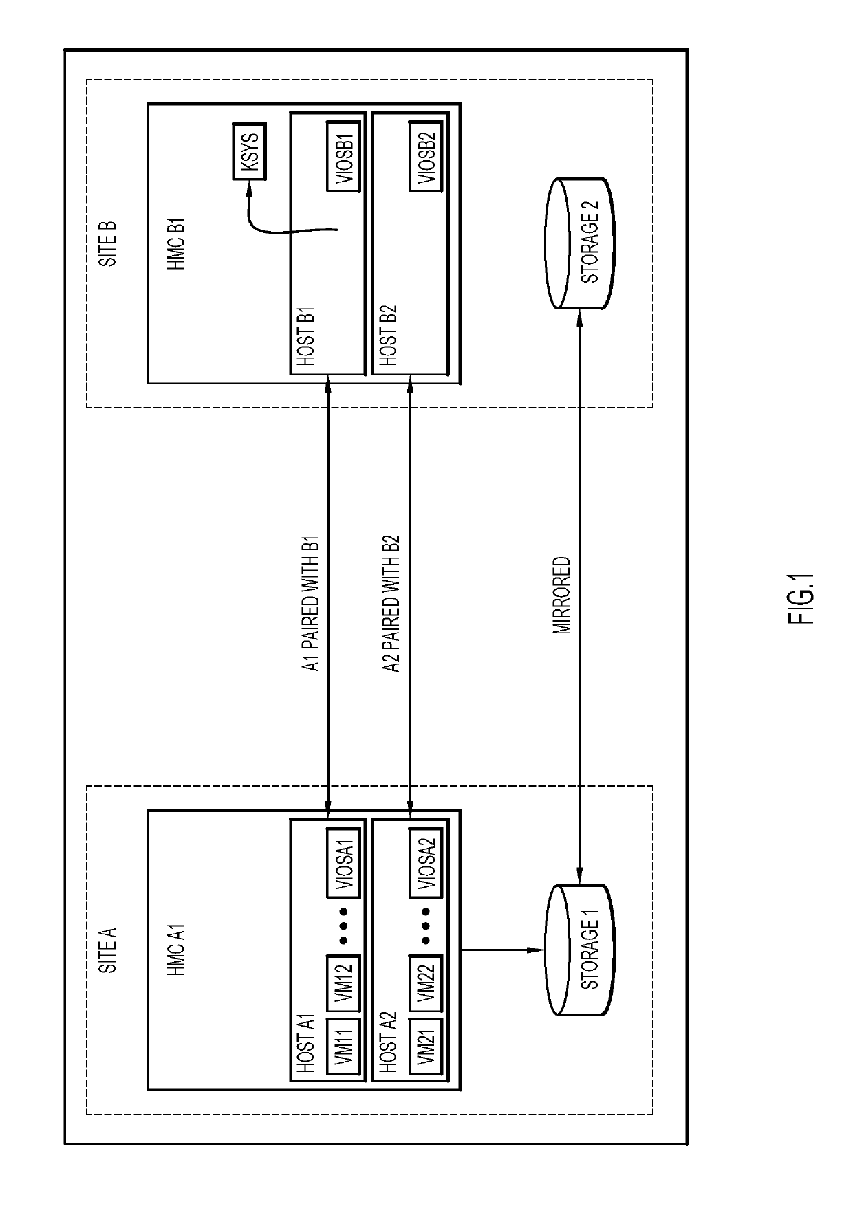
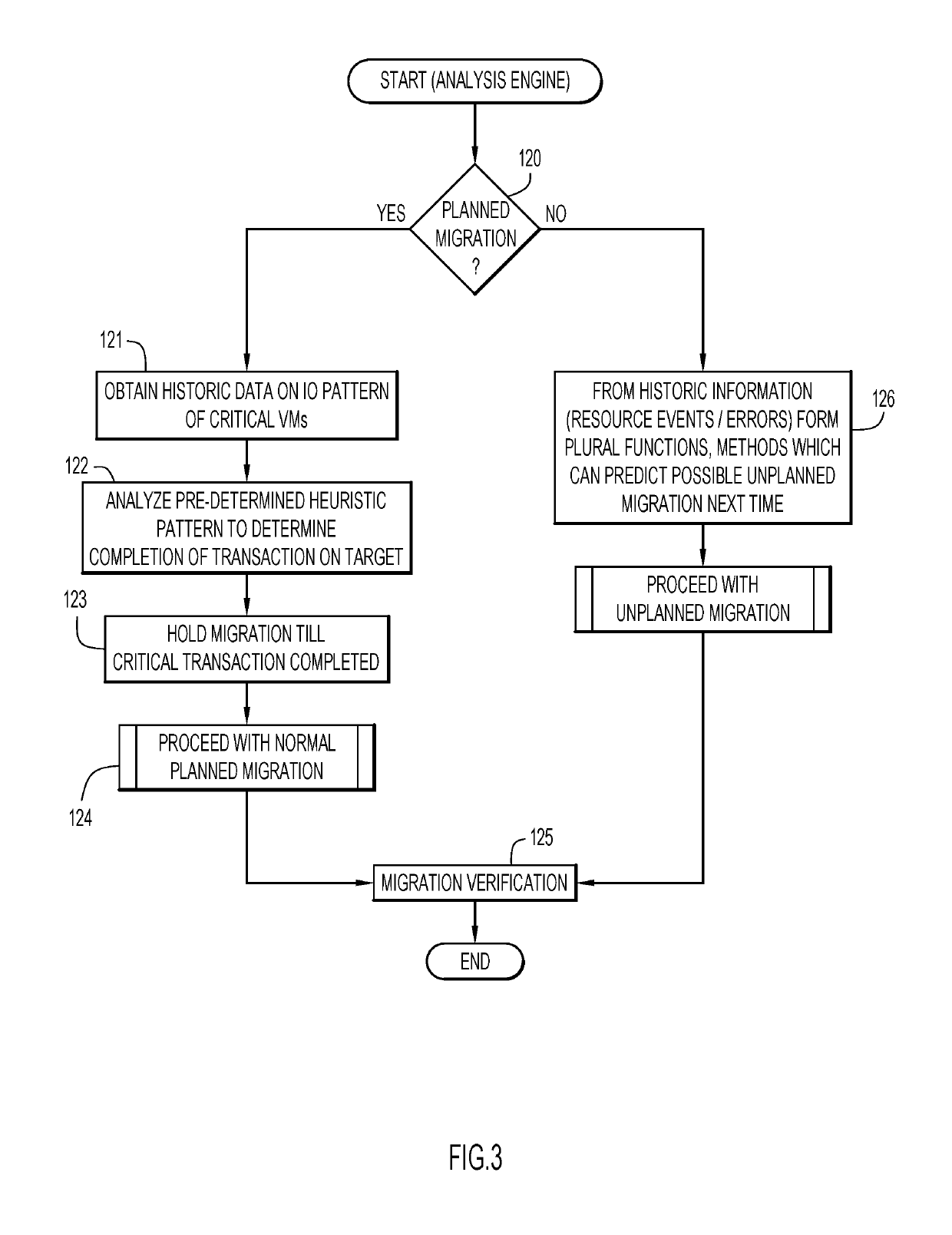
[0019]Reference is now made to FIGS. 1-3 which illustrate a first example of a cognitive rolling disaster recovery solution comprising an orchestrator node or control system KSYS in which a manager application functions. In FIG. 1 the control system KSYS is shown managing two data sites A and B which are logical entities and may be comprised of hardware management consoles (HMC A1 and HMC B1), hosts (Host A1, Host A2, Host B1 and Host B2), virtual I / O servers (VIOSA1, VIOSA2. VIOSB1 and VIOSB2), and virtual machines (VM11, VM12, VM21, VM22) as its resources. The hosts at a primary site are paired with the hosts of a target site such that, for planned or unplanned disaster recovery procedures, the VMs belonging to the primary host will be brought up on the paired host at the target site.

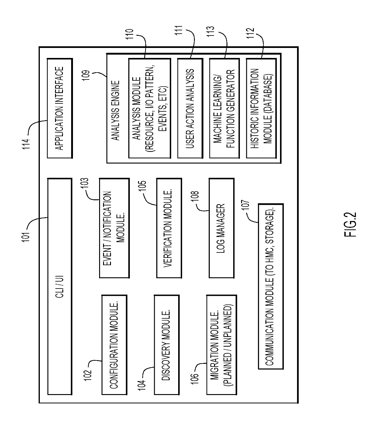
[0020]The embodiment includes various modules as shown in FIG. 2. A user can specify the site (e.g., site A), HMC, host and the paired host information using interface 101 (a user interface UI or comm...


PUM


Abstract

In a system having at least two data storage and processing sites, each capable of alternatively serving as a primary site and a backup or target site, disaster recovery migration is optimized by cognitively analyzing at least one system parameter. Using machine learning, at least one pattern of that system related parameter is predicted, and planned or unplanned migration procedures are performed based on the predicted parameter patterns. The analyzed parameter may be data traffic at the sites, and the predicted data traffic pattern is used to assign primary and backup site status to those sites. The analyzed parameter may be the occurrence of events or transactions at the sites, and the predicted event or transaction patterns may be used to determine times of disaster recovery procedure processing so as to not interrupt a critical event or transaction.

Description

BACKGROUND1. Technical Field[0001]Present invention embodiments relate to data disaster recovery and, more specifically, to cognitive analysis of operational, environmental and resource parameters to improve the recovery time objective (RTO) and recovery point objective (RPO) in disaster recovery migration procedures.2. Discussion of the Related Art[0002]Most systems for effecting disaster recovery, whether planned (such as a scheduled site migration) or unplanned (such as an accidental event), provide techniques wherein resources, such as data storage and processing facilities, are automatically replicated and synchronized at a remote backup or target site such that, when a disaster occurs at a primary site, the resources at a target site are brought online. It is generally the goal in disaster recovery systems to provide optimum recovery time objective (RTO) and recovery point objective (RPO). As part of the disaster recovery process, the following issues need to be addressed:[000...

Claims


Application Information

Patent Timeline
Patent Type & Authority Applications(United States)
IPC IPC(8): G06F11/07G06N99/00G06N5/02
CPCG06N20/00G06F11/0793G06F11/0751G06N5/02G06F11/079G06F11/0709G06F11/2097G06F11/2094G06F11/2035G06F11/2048G06F11/203
Inventor CHITTIGALA, JES KIRANJOSHI, SANTHOSHKUCHERLAPATI, SRIRAMA R.
Owner IBM CORP
Why Eureka
Eureka Blog
Learn More