
Wireless terminal measurement apparatus, circularly polarized antenna device connectable thereto and wireless terminal measurement method

a technology of antenna device and measurement apparatus, which is applied in the direction of polarised antenna unit combination, receiver monitoring, and transmitter monitoring, etc., can solve the problems of large loss, difficult to greatly shorten the time required for connecting the dut to the measurement apparatus by coaxial cable, and limited time that can be spent for each dut, etc., to suppress an amplitude error and accurate measurement

Active Publication Date: 2019-07-18
ANRITSU CORP
View PDF9 Cites 2 Cited by
  • Summary
  • Abstract
  • Description
  • Claims
  • Application Information

AI Technical Summary

Benefits of technology

The present invention provides a device and method for accurately measuring wireless terminals by reducing errors caused by multiple reflections between the wireless terminal's antenna and a circularly polarized antenna. This improves the accuracy of wireless terminal measurements.

Problems solved by technology

Although the performance tests on tens of thousands of DUTs per day can be requested, the time that can be spent for each DUT is limited.
However, it is difficult to greatly shorten the time required for connecting the DUT to the measurement apparatus by coaxial cables because the physical connection via the coaxial cables is made by the user.
Further, in the case where an antenna of the DUT radiates a wireless signal or radio signal of K-band or Ka-band (18 GHz to 40 GHz), the configuration that the antenna terminal of the DUT and the measurement apparatus are connected by a coaxial cable causes a large loss during transmission of a signal from the antenna of the DUT to the measurement apparatus through the coaxial cable.
Accordingly, there has been a problem that accurate measurements cannot be performed in such cases.

Method used


Image

  • Wireless terminal measurement apparatus, circularly polarized antenna device connectable thereto and wireless terminal measurement method
  • Wireless terminal measurement apparatus, circularly polarized antenna device connectable thereto and wireless terminal measurement method
  • Wireless terminal measurement apparatus, circularly polarized antenna device connectable thereto and wireless terminal measurement method

Examples


first embodiment

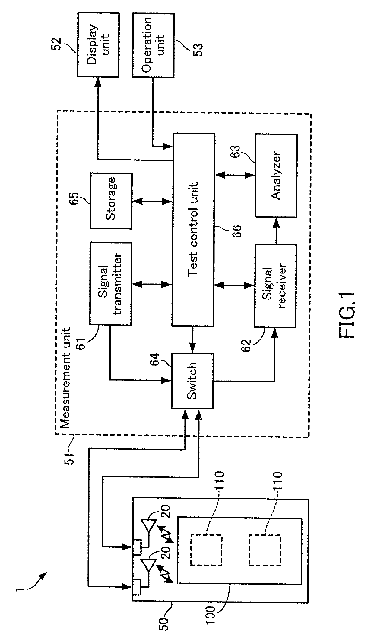
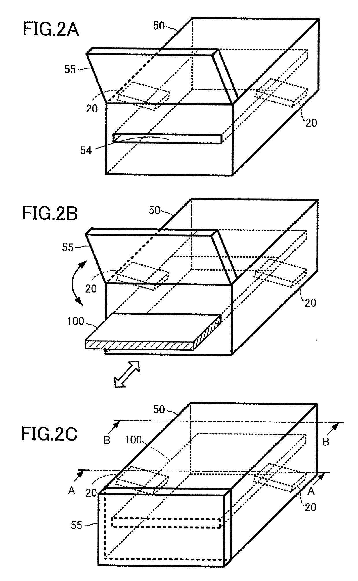
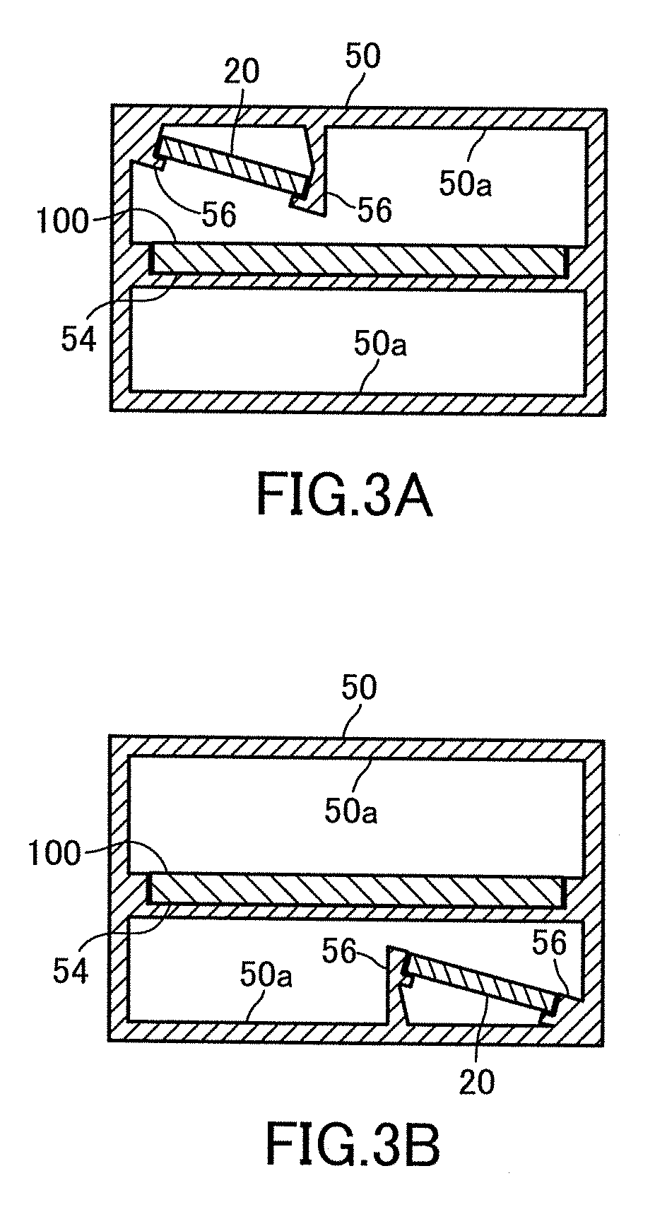
[0063]As shown in FIG. 1, a wireless terminal measurement apparatus 1 according to the first embodiment of the present invention inputs a test signal to a device under test (DUT) 100 having one or more antennas 110, and measures a response signal output from the DUT 100 to obtain transmission and reception characteristics. For example, the wireless terminal measurement apparatus 1 includes circularly polarized antennas 20, a terminal holder 50, a measurement unit 51, a display unit 52, and an operation unit 53. Here, the circularly polarized antennas 20 and the terminal holder 50 constitute a circularly polarized antenna device connectable to the wireless terminal measurement apparatus 1.

[0064]The DUT 100 is a wireless terminal such as a smartphone. Examples of communication standards for the DUT 100 include, but are not limited to, cellular system (LTE, LTE-A, W-CDMA (registered trademark), GSM (registered trademark), CDMA2000, 1×EV-DO, TD-SCDMA, and the like), wireless LAN (IEEE 8...

second embodiment

[0153]A wireless terminal measurement apparatus 2 according to a second embodiment of the present invention will be described hereinafter with reference to the drawings. Note that the same reference numerals are given to the same configurations as those of the first embodiment, and the description thereof will be omitted. Further, the description of operations similar to those in the first embodiment will also be omitted.

[0154]As shown in FIG. 22, the wireless terminal measurement apparatus 2 of the present embodiment includes a belt conveyor 81, an electromagnetic wave shield box 82 as a measurement box, a drive control unit 83, a measurement unit 51, a display unit 52, and an operation unit 53.

[0155]The electromagnetic wave shield box 82 hits an entrance 82a and an exit 82b for conveying the DUT 100, and covers a space including at least a part of a conveying path 81a. The electromagnetic wave shield box 82 internally included one or more circularly polarized antennas 20 to be spa...


PUM


Abstract

A circularly polarized antenna device, which is connectable to a wireless terminal measurement apparatus for performing measurements on a device under test (DUT) provided with an antenna on one surface of the DUT, includes a circularly polarized antenna and a holder. The circularly polarized antenna includes a dielectric substrate and a circularly polarized type of antenna element formed on a first surface of the dielectric substrate. The first surface is opposite to the one surface of the DUT. The circularly polarized antenna is spatially coupled to the antenna of the DUT. The holder holds the circularly polarized antenna and the DUT such that the one surface of the DUT and the dielectric substrate are not parallel to each other.

Description

CROSS-REFERENCE TO RELATED APPLICATIONS[0001]This application is based upon and claims the benefit of priority from prior Japanese Patent Application No. 2017-150113 filed Aug. 2, 2017, the entire contents of which are incorporated herein by reference.BACKGROUND OF THE INVENTION1. Field of the Invention[0002]The present invention relates to wireless terminal measurement apparatuses used with circularly polarized antennas, circularly polarized antenna devices connectable to the wireless terminal measurement apparatuses, and wireless terminal measurement methods.2. Description of Related Art[0003]In recent years, wireless terminals (smart phones or the like) having antennas attached therein for wireless communication, such as cellular communication and wireless LAN, have been actively produced with the progress of multimedia. In the future, there will be much demand for wireless terminals that transmits and receives broadband wireless signals conforming to IEEE802.1lad, 5G cellular st...

Claims


Application Information

Patent Timeline
IPC IPC(8): H01Q9/04H01Q21/24H01Q9/27
CPCH01Q9/0428H01Q21/24H01Q9/27H04B17/15H04B17/29H01Q1/36H01Q21/06H01Q1/243
Inventor KUROIWA, YOSHIHIROYAMAMOTO, AYAMORITA, TOMONORI
Owner ANRITSU CORP
Learn More