
Master control device and synchronous communication system using same

a control device and synchronous communication technology, applied in the direction of data switching networks, multiplex communication, digital transmission, etc., can solve the problems of inability to accurately synchronize the times of the respective control devices, the delay of processing or the like within a central processing unit other than communication is not taken into account, and cannot achieve synchronization with the real tim

Active Publication Date: 2019-07-18
MITSUBISHI ELECTRIC CORP
View PDF17 Cites 9 Cited by
  • Summary
  • Abstract
  • Description
  • Claims
  • Application Information

AI Technical Summary

Benefits of technology

The present invention aims to provide a master control device that can confirm timing synchronization of multiple slave control devices connected via a network, which can include a master local time in a message and receive a message from a slave control device at a corrected timing. The invention also includes a timing correction amount calculation unit to confirm synchronization and make corrections if needed. This invention enables better timing synchronization and communication between multiple devices connected via a network.

Problems solved by technology

This means that the timers in the closed system are synchronized, so that synchronization with the real time cannot be achieved.
In addition, correction due to a delay of communication is performed, but a delay of processing or the like within a central processing unit (CPU) other than communication is not taken into consideration.
Thus, an error is included in the local timer value transmitted by each control device, and if the respective local timer values include different errors, there is a possibility that times of the respective control devices are not accurately synchronized.
However, Patent Document 2 does not disclose a specific method for calculating a time lag and taking the time lag into consideration.
However, similar to Patent Document 1, a delay time until a master control device completes transmission of a message and a delay time until each slave control device sends a notification of reception of the message are taken into consideration, but delays other than a calculation processing delay and a communication delay are not taken into consideration.
Moreover, each slave control device includes a means for confirming synchronization with the received local time of the master control device, but the received local time of the master control device includes uncertainties, and thus synchronization with this local time cannot necessarily be considered to ensure proper synchronization between the master control device and the slave control device.

Method used


Image

  • Master control device and synchronous communication system using same
  • Master control device and synchronous communication system using same
  • Master control device and synchronous communication system using same

Examples


embodiment 1

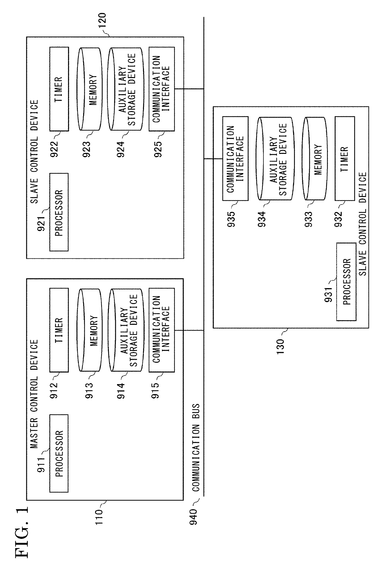
[0039]Hereinafter, an embodiment of a synchronous communication system will be described with reference to the drawings.

[0040]FIG. 1 is a schematic configuration diagram showing a synchronous communication system according to Embodiment 1 of the present invention.

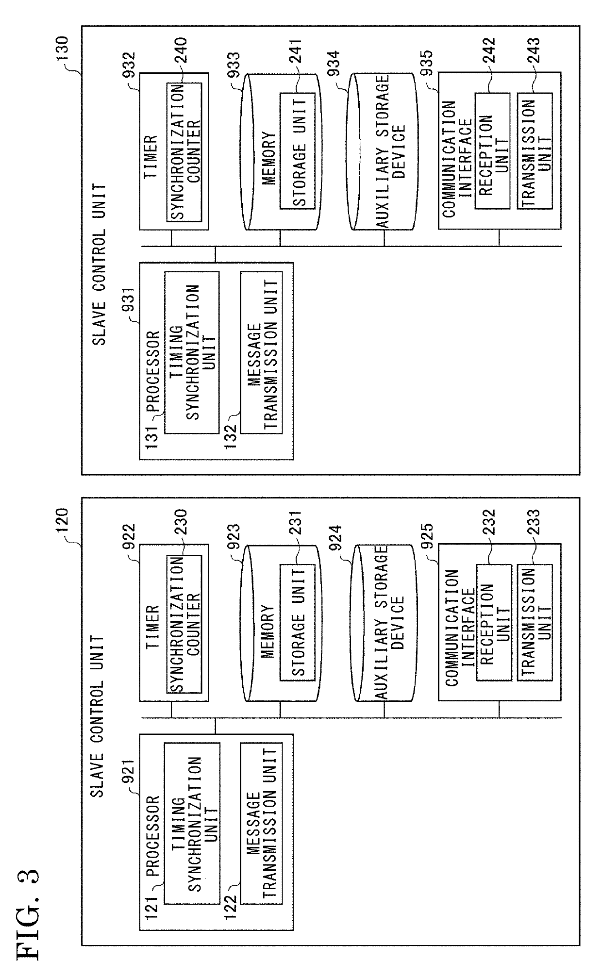
[0041]In FIG. 1, the synchronous communication system includes a master control device 110, a slave control device 120, and a slave control device 130. The master control device 110, the slave control device 120, and the slave control device 130 are connected to each other by a communication bus 940, for example, a control area network (CAN) bus.

[0042]The master control device 110, the slave control device 120, and the slave control device 130 are collectively referred to as control devices.

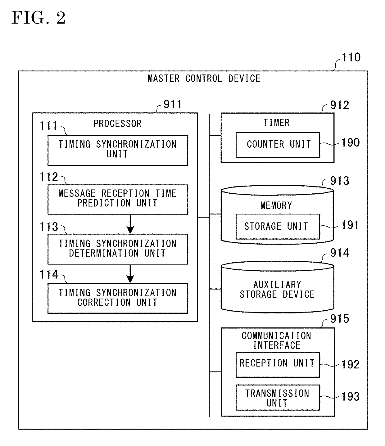
[0043]The master control device 110 is configured as follows.

[0044]The master control device 110 includes hardware devices, that is, a processor 911, a timer 912, a memory 913, an auxiliary storage device 914, and a communication interfa...


PUM


Abstract

A master control device connected to a plurality of slave control devices via a network is configured to include an own local time counted by a counter unit, in a message and transmit the message to the slave control devices by the timing synchronization unit, calculate a difference between a reception time of a message transmitted from the slave control device, which has received the message, at a timing corrected in accordance with the local time and a pre-calculated message reception predicted time by a timing synchronization determination unit, calculate a correction amount for timing of the slave control devices using the difference by a timing synchronization correction unit, add the correction amount to the local time, include the local time in a message, and transmit the message to the slave control devices.

Description

BACKGROUND OF THE INVENTION1. Field of the Invention[0001]The present invention relates to a master control device that performs timing synchronization of a plurality of control devices connected thereto via a network, and a synchronous communication system using the master control device.2. Description of the Background Art[0002]In recent years, in a system in which a plurality of control devices are connected via a network and perform communication, for example, in a vehicle or the like, the respective control devices exchange data therebetween and control is required to be performed by combining these data.[0003]Generally, each control device is equipped with an independent timer and determines timing of calculation or control processing on the basis of the timer. In the case where a plurality of control devices operate in conjunction with each other, it is necessary to synchronize timing of calculation or control processing of each control device.[0004]In particular, in a contro...

Claims


Application Information

Patent Timeline
IPC IPC(8): H04L7/00H04L12/403H04L12/26
CPCH04L7/0054H04L7/0037H04L12/403H04L43/0858H04L12/40019H04J3/0664
Inventor YOSHIDA, MIKIYAISHIHARA, KENTAROMATSUI, TOSHINORI
Owner MITSUBISHI ELECTRIC CORP
Learn More