

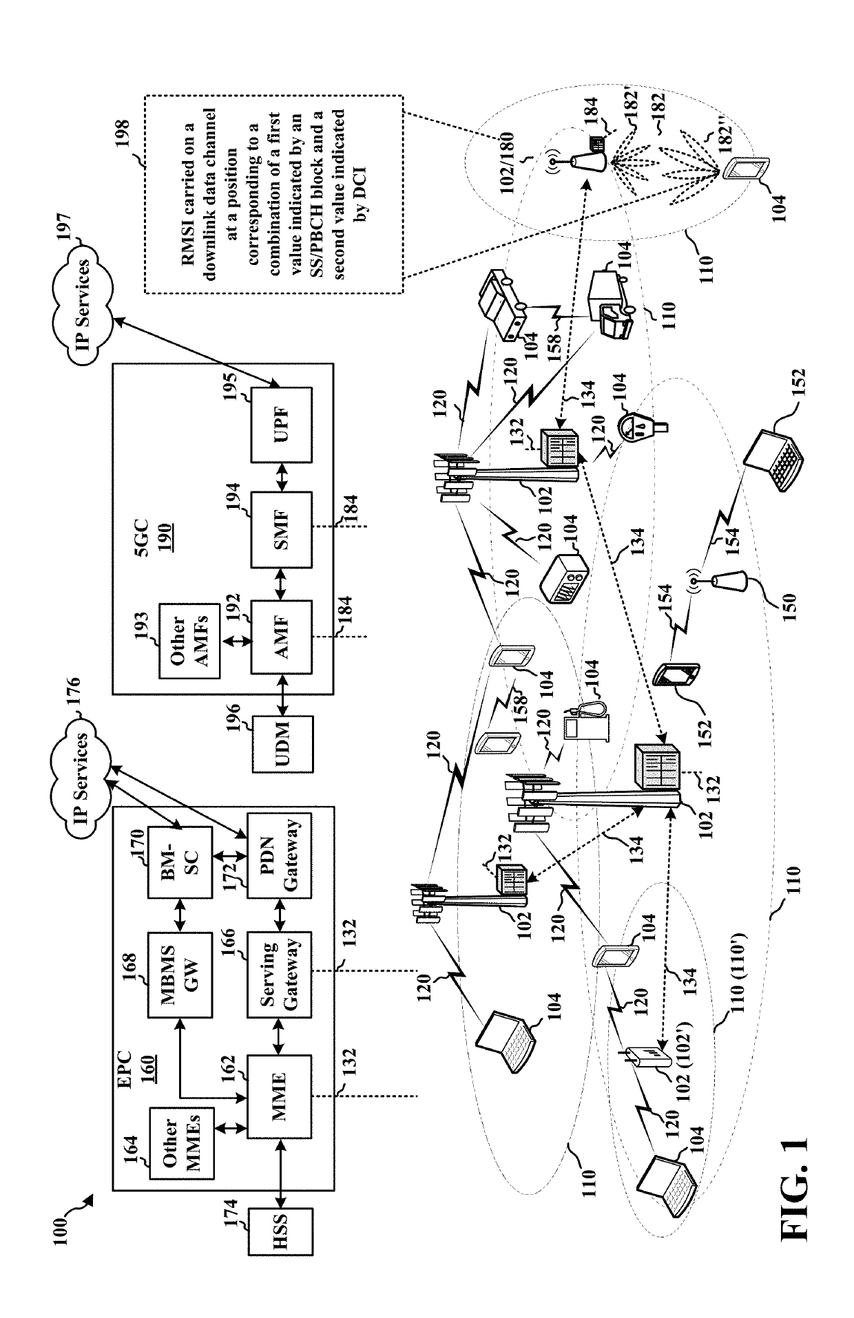
System and method for locating a downlink data channel
a data channel and data system technology, applied in the field of communication systems, can solve the problems of not indicating all, incurring overhead that may be unsuitable for one or more rats, and the cost of signaling a bitmap indicating time domain patterns may be relatively high with respect to over-the-air signaling, so as to reduce over-the-air signaling and exceed the capacity of dci messaging
- Summary
- Abstract
- Description
- Claims
- Application Information
AI Technical Summary
Benefits of technology
Problems solved by technology
Method used
Image

Examples
Embodiment Construction
[0024]The detailed description set forth below in connection with the appended drawings is intended as a description of various configurations and is not intended to represent the only configurations in which the concepts described herein may be practiced. The detailed description includes specific details for the purpose of providing a thorough understanding of various concepts. However, it will be apparent to those skilled in the art that these concepts may be practiced without these specific details. In some instances, well known structures and components are shown in block diagram form in order to avoid obscuring such concepts.
[0025]Several aspects of telecommunication systems will now be presented with reference to various apparatus and methods. These apparatus and methods will be described in the following detailed description and illustrated in the accompanying drawings by various blocks, components, circuits, processes, algorithms, etc. (collectively referred to as “elements...
PUM
 Abstract
Description
Claims
Application Information