
Systems and methods for controlling motion of detectors having moving detector heads

a detector head and motion control technology, applied in the field of diagnostic medical imaging, can solve problems such as radiation exposure to patients, known system radiation resolution degradation, and resolution degradation, and achieve the effect of reducing imaging resolution

Active Publication Date: 2019-07-25
GE PRECISION HEALTHCARE LLC
View PDF0 Cites 5 Cited by
  • Summary
  • Abstract
  • Description
  • Claims
  • Application Information

AI Technical Summary

Benefits of technology

This approach improves image quality by reducing acquisition time, increasing resolution in regions of interest, and allowing for closer placement of detectors, thereby minimizing radiation exposure and enhancing overall imaging efficiency.

Problems solved by technology

This increase in distance results in a degrading of resolution.
Thus, known systems have degradation in imaging resolution as a result of the limits to which the gamma cameras can move in proximity to the subject because of the configuration of the detector head or collimator used, and / or the types of control of movement of the gamma cameras.
Further, known systems may expose patients to levels of radiation that is higher than necessary.

Method used


Image

  • Systems and methods for controlling motion of detectors having moving detector heads
  • Systems and methods for controlling motion of detectors having moving detector heads
  • Systems and methods for controlling motion of detectors having moving detector heads

Examples


Embodiment Construction

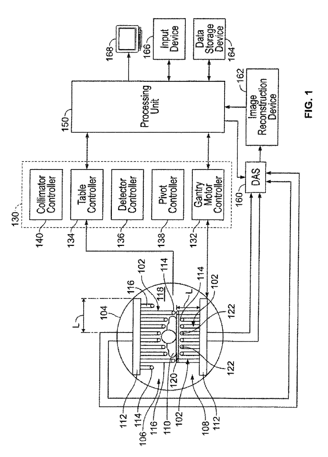
[0045]The following detailed description of certain embodiments will be better understood when read in conjunction with the appended drawings. To the extent that the figures illustrate diagrams of the functional blocks of various embodiments, the functional blocks are not necessarily indicative of the division between hardware circuitry. For example, one or more of the functional blocks (e.g., processors or memories) may be implemented in a single piece of hardware (e.g., a general purpose signal processor or a block of random access memory, hard disk, or the like) or multiple pieces of hardware. Similarly, the programs may be stand alone programs, may be incorporated as subroutines in an operating system, may be functions in an installed software package, and the like. It should be understood that the various embodiments are not limited to the arrangements and instrumentality shown in the drawings.

[0046]As used herein, the terms “system,”“unit,” or “module” may include a hardware a...


PUM


Abstract

An imaging system is provided that includes a gantry, at least five detector units mounted to the gantry, a corresponding collimator for each of the detector units, at least one processing unit, and a controller. Each collimator has septa defining plural bores for each pixel of at least some of a plurality of pixels of the detector unit. A corresponding interior septum of the collimator is disposed above an internal portion of a corresponding pixel of the at least some of the plurality of pixels. The at least one processing unit is configured to obtain object information corresponding to the object to be imaged. The controller is configured to control an independent rotational movement of each the detector units used to acquire scanning information by detecting emissions from the object, wherein the controller rotates each of the detector units at a corresponding sweep rate.

Description

RELATED APPLICATIONS[0001]The present application is a continuation application of U.S. patent application Ser. No. 14 / 140,052, entitled “SYSTEMS AND METHODS FOR CONTROLLING MOTION OF DETECTORS HAVING MOVING DETECTOR HEADS,” (the 052 application) filed Dec. 24, 2013, the content of which is incorporated herein by reference in its entirety. The 052 application is a continuation-in-part application of U.S. patent application Ser. No. 14 / 040,108, entitled “SYSTEMS AND METHODS FOR CONTROLLING MOTION OF DETECTORS HAVING MOVING DETECTOR HEADS,” filed Sep. 27, 2013, the content of which is incorporated herein by reference in its entirety.BACKGROUND OF THE INVENTION[0002]The subject matter disclosed herein relates generally to apparatus and methods for diagnostic medical imaging, such as Nuclear Medicine (NM) imaging.[0003]In NM imaging, systems with multiple detectors or detector heads may be used to image a subject, such as to scan a region of interest. For example, the detectors may be p...

Claims


Application Information

Patent Timeline
Patent Type & Authority Applications(United States)
IPC IPC(8): A61B6/00A61B6/03A61B6/06
CPCA61B6/4266A61B6/545A61B6/544A61B6/4258A61B6/037A61B6/54A61B6/06A61B6/0407
Inventor BOUHNIK, JEAN-PAULRAFAELI, TZACHIKOVALSKI, GILGROBSHTEIN, YARIVMAHAMEED, RIYADHEFETZ, YARONBINYAMIN, EINATZINGERMAN, YULIMWARTSKI, NURIT RIVKA
Owner GE PRECISION HEALTHCARE LLC
Learn More