
Drum motor with alternative transmission mount

a technology of motor drive and transmission mount, which is applied in the direction of conveyors, conveyors, transportation and packaging, etc., can solve the problems of high load on the gearing and torque-transmitting components, insufficient load on the construction, and complex matching in terms of production, so as to prevent the assembly error of the motor-driven conveyor roller, reduce the cost of storage of spare parts, and prevent the effect of failur

Active Publication Date: 2019-07-25
INTERROLL HLDG
View PDF6 Cites 0 Cited by
  • Summary
  • Abstract
  • Description
  • Claims
  • Application Information

AI Technical Summary

Benefits of technology

The invention is a method for producing conveyor rollers that use force-fitting connections between gearing and gearing connection sections, which are particularly useful for large torque transmission and highly accurate rotation positioning. The method is advantageous because it allows for the production of conveyor rollers with high variability in gearing options, at low production costs and without the need for extensive storage. The use of plastic gearings in these connections has proven to be unreliable over the long term due to deformation caused by a high degree of pressing, but the method maintains a high level of pressing for the force-fitting connection, which prevents this issue. Additionally, the method addresses the issue of high temperatures that can occur in conveyor rollers, which further amplifies the deformation issue.

Problems solved by technology

In this regard, in addition to the drive motor, the gearing and the torque-transmitting components are subjected to high loads, these, however, being of different types, if on the one hand a motor-driven conveyor roller is configured with a particularly high rotational speed, or if on the other hand a motor-driven conveyor roller is configured with a particularly high torque.
Firstly, the gearing accounts for a large proportion of the running noises generated by a conveyor roller.
However, this construction is not able to bear loads sufficiently, in particular, if very large torques are transmitted, and so gearings produced from metallic materials have proven to be successful for conveyor rollers that are designed for a large torque.
A problem that arises is that this matching is complex in terms of production, and precisely when gearings from the extremes of the design spectrum, that is to say, having either a very high speed at the gearing output or a very large torque at the gearing output, are used, no satisfactory transmission of the torque from the gearing output to the conveyor roller tube is achieved.

Method used


Image

  • Drum motor with alternative transmission mount
  • Drum motor with alternative transmission mount
  • Drum motor with alternative transmission mount

Examples


Embodiment Construction

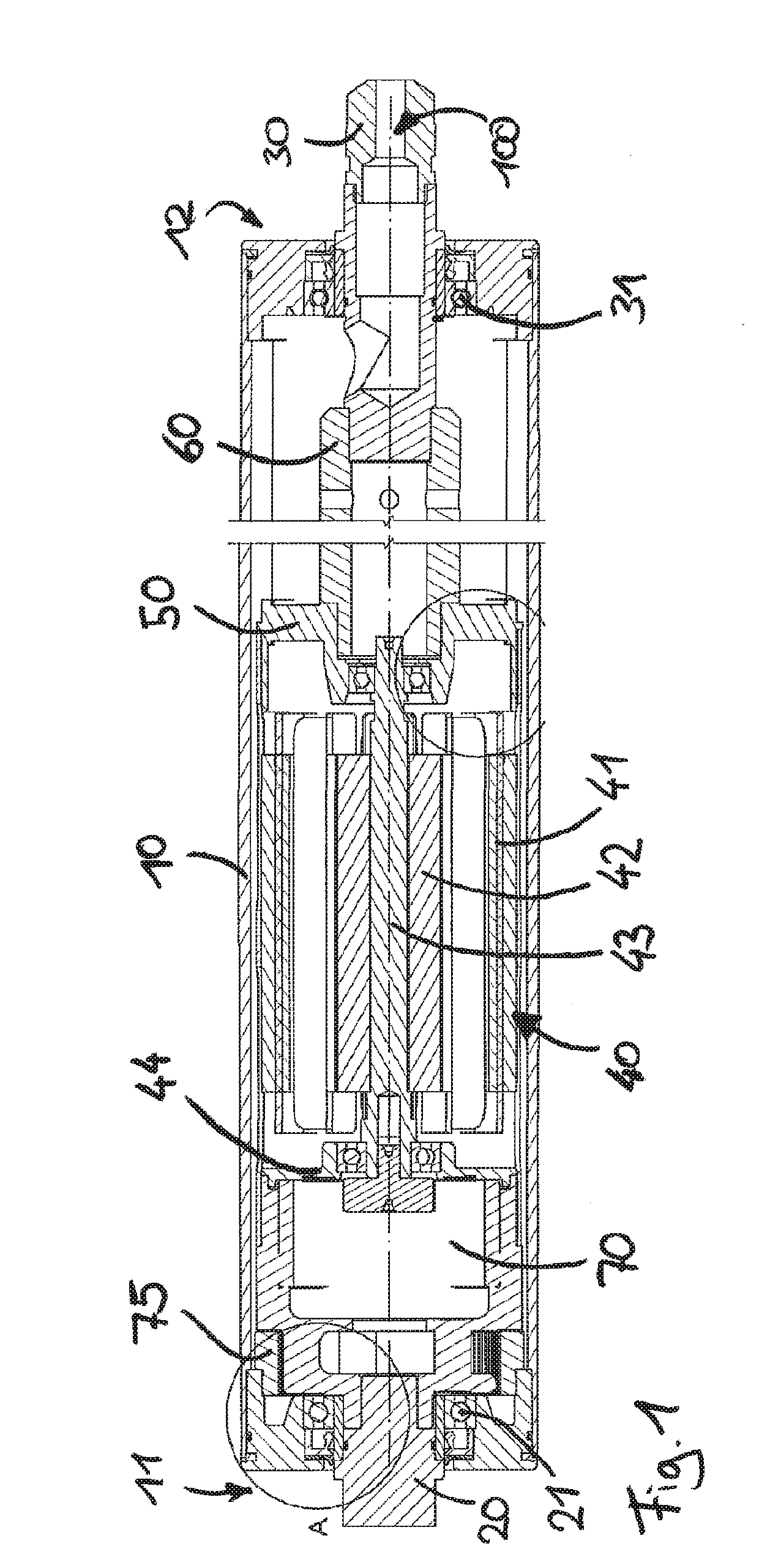
[0052]The basic construction of a motor-driven conveyor roller or of a drum motor can be seen from FIG. 1. A conveyor roller tube 10 extends longitudinally from a first end 11 to a second end 12. In the conveyor roller tube 10, a first axle unit 20 is arranged at the first end and a second axle unit 30 is arranged at the second end 12, said axle units 20, 30 being mounted rotatably relative to the conveyor roller tube 10 by means of ball bearings 21, 31. Consequently, the conveyor roller tube 10 can rotate around the axle units 20, 30, which in this case define an axis of rotation 100.

[0053]Also arranged in the conveyor roller tube 10 is an electric motor 40, which is designed as a synchronous motor. The stator 41 of the electric motor 40 is coupled fixedly in terms of torque to the second axle unit 30 by means of an intermediate flange 50, and an extension piece 60 and can thereby be held positionally fixed by means of the second axle unit 30. The electric motor 40 comprises a stat...


PUM


Abstract

A motor-driven conveyor roller comprises a conveyor roller tube, a first axle unit inserted into a first end of the conveyor roller tube, a first bearing unit at the first end, around which the conveyor roller tube is mounted so as to be correspondingly rotatable around the first axle unit, a drive unit, and a first gearing arranged in the conveyor roller tube and which transmits a torque, generated by the drive unit, between the conveyor roller tube and the first axle unit.An end cap is connected fixedly in terms of torque to the conveyor roller tube at the first end and to which the first gearing is connected fixedly in terms of torque at a first gearing connection section of the end cap, wherein the end cap has a second gearing connection section, which is different from the first gearing connection section.

Description

CROSS-REFERENCE TO FOREIGN PRIORITY APPLICATION[0001]The present application claims the benefit under 35 U.S.C. §§ 119(b), 119(e), 120, and / or 365(c) of PCT / EP2017 / 066173 filed Jun. 29, 2017, which claims priority to German Application No. 102016112054.5 filed Jun. 30, 2016.FIELD OF THE INVENTION[0002]The invention relates to a motor-driven conveyor roller comprising: a conveyor roller tube, a first axle unit, which is inserted into a first end of the conveyor roller tube, a first bearing unit at the first end, around which the conveyor roller tube is mounted so as to be correspondingly rotatable around the first axle unit, a drive unit, and a first gearing, which is arranged in the conveyor roller tube and which transmits a torque, generated by the drive unit, between the conveyor roller tube and the first axle unit. A further aspect of the invention is a conveyor roller system and a method for producing a motor-driven conveyor roller.FIELD OF THE INVENTION[0003]Motor-driven convey...

Claims


Application Information

Patent Timeline
IPC IPC(8): B65G23/08
CPCB65G23/08B65G13/06
Inventor MANS, ERWIN
Owner INTERROLL HLDG
Features
  • Generate Ideas
  • Intellectual Property
  • Life Sciences
  • Materials
  • Tech Scout
  • Unparalleled Data Quality
  • Higher Quality Content
  • 60% Fewer Hallucinations
Learn More