High pressure tank structure
a high-pressure tank and structure technology, applied in the direction of vessel construction details, container discharging methods, electrochemical generators, etc., can solve the problems of less thermal conductivity of resin-made liner than that of a liner, more difficult for heat of a portion exposed to a flame to be promptly directed to the pressure relief device, and the thermal degradation of the reinforced layer will be more easily advanced. , to achieve the effect of improving the durability of the high-pressure tank, facilitating th
- Summary
- Abstract
- Description
- Claims
- Application Information
AI Technical Summary
Benefits of technology
Problems solved by technology
Method used
Image
Examples
first embodiment
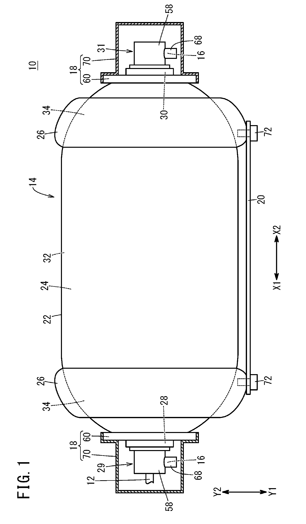
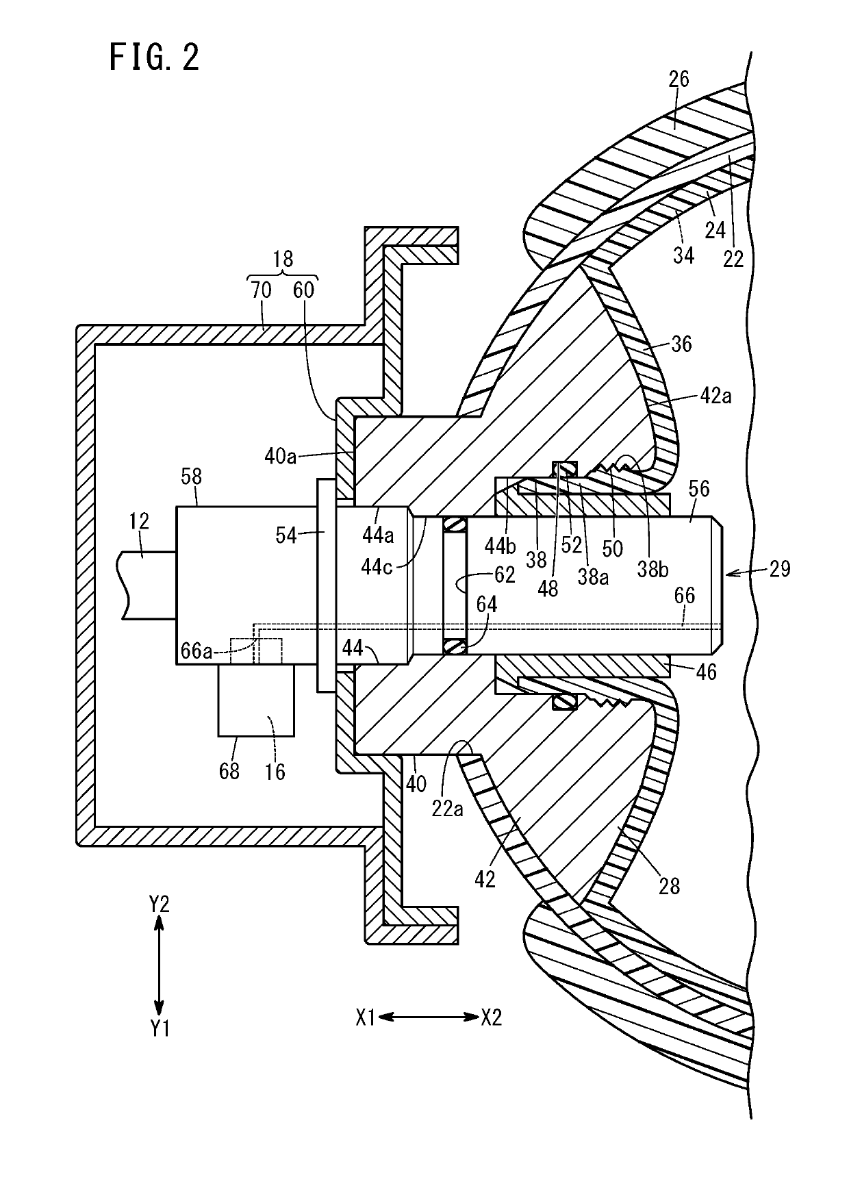
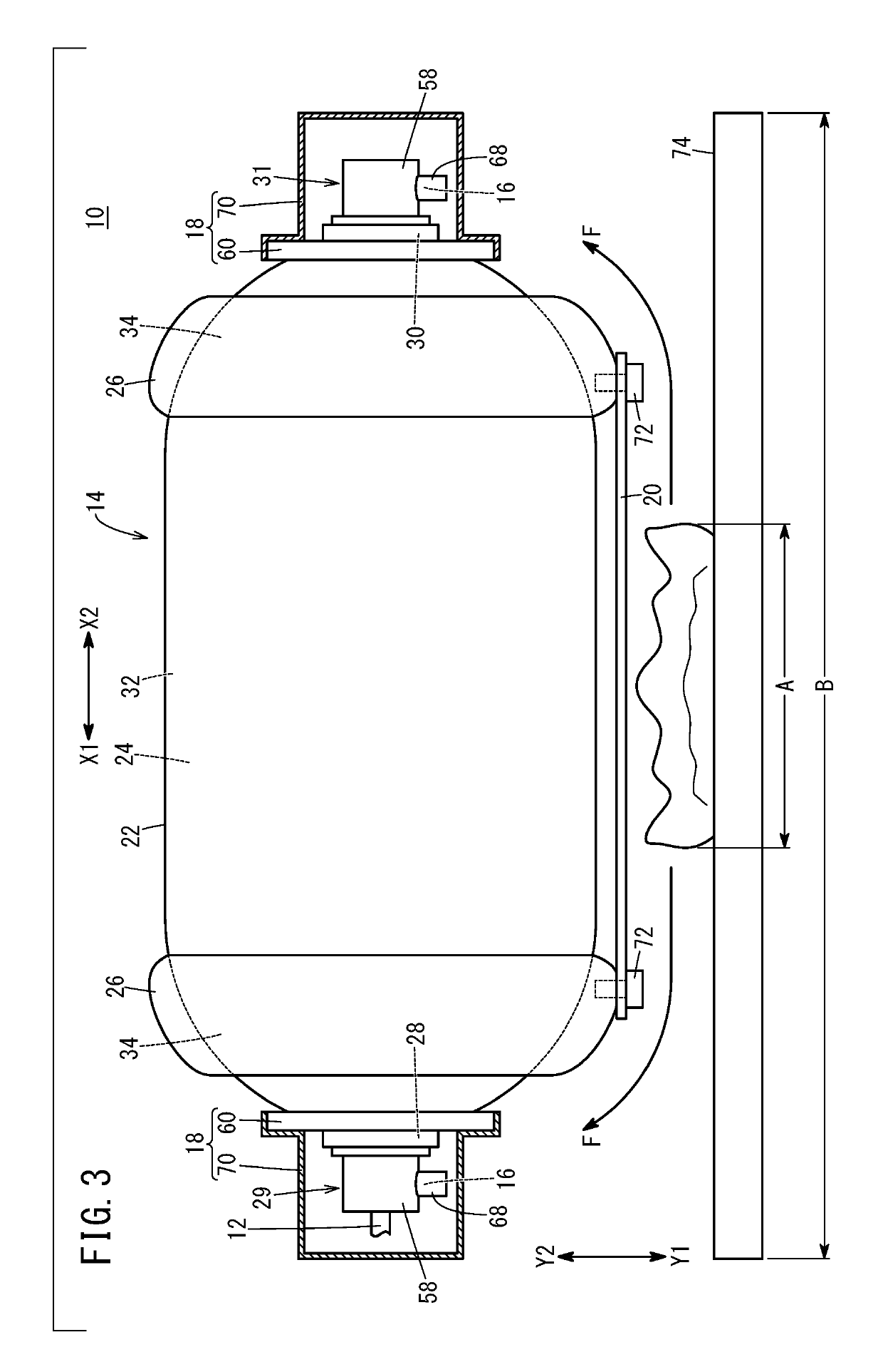
[0045]As shown in FIG. 1, in the first embodiment, the heat-resistant plate 20 is in the form of a plate configured from a heat-resistant metal such as iron or a fireproof fabric, for example, and is integrally attached to the high pressure tank 14 via the protective member 26, so as to be disposed facing the reinforced layer 22 at least on the bottom surface side. In other words, the heat-resistant plate 20 is fixed to the protective member 26. Although a method of fixing the protective member 26 and the heat-resistant plate 20 is not particularly limited, the four corners of the heat-resistant plate 20 may be screw-fastened to the protective member 26 using bolts 72 or the like (refer to FIG. 1), for example.
[0046]As will be mentioned later, from a viewpoint of suppressing heat conduction to the reinforced layer 22 occurring from the heat-resistant plate 20 when the heat-resistant plate 20 is exposed to a flame, and so on, the heat-resistant plate 20 and the reinforced layer 22 ar...
second embodiment
[0060]In the high pressure tank structure 80 configured as described above, heat of the heat-resistant plate 20 whose temperature has risen by being exposed to a flame can be efficiently transmitted to the pressure relief device 16 via the attaching members 82 and the installing sections 68. Therefore, the pressure relief device 16 can be more favorably operated.
[0061]Next, a high pressure tank structure 90 according to a third embodiment will be described with reference to FIG. 5. The high pressure tank structure 90 is configured similarly to the high pressure tank structure 10 according to the first embodiment, apart from the heat-resistant plate 20 being integrally attached to the high pressure tank 14 via the partitioning wall sections 18.
[0062]Specifically, the heat-resistant plate 20 is attached to the high pressure tank 14 so as to be disposed as described above, by each of attaching members 92 whose one end section 92a is fixed to the heat-resistant plate 20 and whose other...
third embodiment
[0064]In the high pressure tank structure 90 configured as described above, it is easy for the heat-resistant plate 20 to be attached to the high pressure tank 14 so as to achieve the above-described arrangement, and it becomes possible for the high pressure tank 14 and the heat-resistant plate 20 to be firmly joined by a simple configuration.
[0065]The present invention is not particularly limited to the above-described embodiments, and may be variously modified in a range not departing from the spirit of the present invention.
[0066]Although in the above-described high pressure tank structures 10, 80, 90 according to the first through third embodiments, the high pressure tank 14 has been configured to include the end-side cap 30, the high pressure tank 14 need not include the end-side cap 30. In this case, the pressure relief device 16 is provided only for the supplying / discharging-side inserting member 29 inserted in the supplying / discharging hole 44 of the supplying / discharging-s...
PUM
| Property | Measurement | Unit |
|---|---|---|
| Temperature | aaaaa | aaaaa |
Abstract
Description
Claims
Application Information
 - R&D
- Intellectual Property
- Life Sciences
- Materials
- Tech Scout
- Unparalleled Data Quality
- Higher Quality Content
- 60% Fewer Hallucinations
Browse by: Latest US Patents, China's latest patents, Technical Efficacy Thesaurus, Application Domain, Technology Topic, Popular Technical Reports.
© 2025 PatSnap. All rights reserved.Legal|Privacy policy|Modern Slavery Act Transparency Statement|Sitemap|About US| Contact US: help@patsnap.com


