System for generating brief or ultra-brief light pulses

Active Publication Date: 2019-08-01
IRISIOME
View PDF0 Cites 1 Cited by
  • Summary
  • Abstract
  • Description
  • Claims
  • Application Information

AI Technical Summary

Benefits of technology

The patent describes a new system for creating light pulses that is more compact, easy to use, and can be adjusted for different needs. Unlike other systems, this one doesn't use any specific way of generating light pulses, making it a bit more unique. Overall, this system can be a great tool for generating light pulses in a compact space and with a wide range of options for duration, repetition rate, and wavelength.

Problems solved by technology

The optical fiber laser systems are now serious competitors to the diode-pumped solid-state lasers.
However, the architectures of these solid-state laser systems are very complex.
These crystal laser systems suffer from drawbacks of sensitivity to changes in the external environment.
These drawbacks are an obstacle to the integration of solid-state lasers into industrial devices.
Although fibre lasers have certain advantages with respect to the solid-state laser, they still suffer from many drawbacks.
Due to this confinement, the light pulses can be source of nonlinear optical effects liable to limit the energy (or the peak power) of a mode-locked fibre laser.
On the other hand, the chromatic dispersion in an optical fibre may also cause dysfunctions, in particular for wavelength-tunable lasers.
This mode locking process remains complex because a significant number of longitudinal modes oscillating in the cavity must be phase aligned.
However, these nonlinear optical methods are not easy to use in wavelength, pulse-duration and / or repetition-frequency tunable laser systems.
It is hence not possible to use only one SESAM over an extended wavelength tunability range.
Moreover, the degrees of freedom for obtaining the mode locking are extremely reduced and require a high level of mastery of this technology.
These optical components being not available in fibre technology, the use thereof involves propagating the beam in free space out of the fibre.
It is hence not possible to make fully-fibred laser sources by this technology.
Moreover, a variation of the fibre birefringence by thermal or mechanical effect degrades the mode locking.

Method used


Image

  • System for generating brief or ultra-brief light pulses
  • System for generating brief or ultra-brief light pulses

Examples


Embodiment Construction

[0045]The following description with respect to the appended drawings, given by way of non-limitative examples, will permit a good understanding of what the invention consists in and of how it can be implemented.

[0046]In the appended drawings:

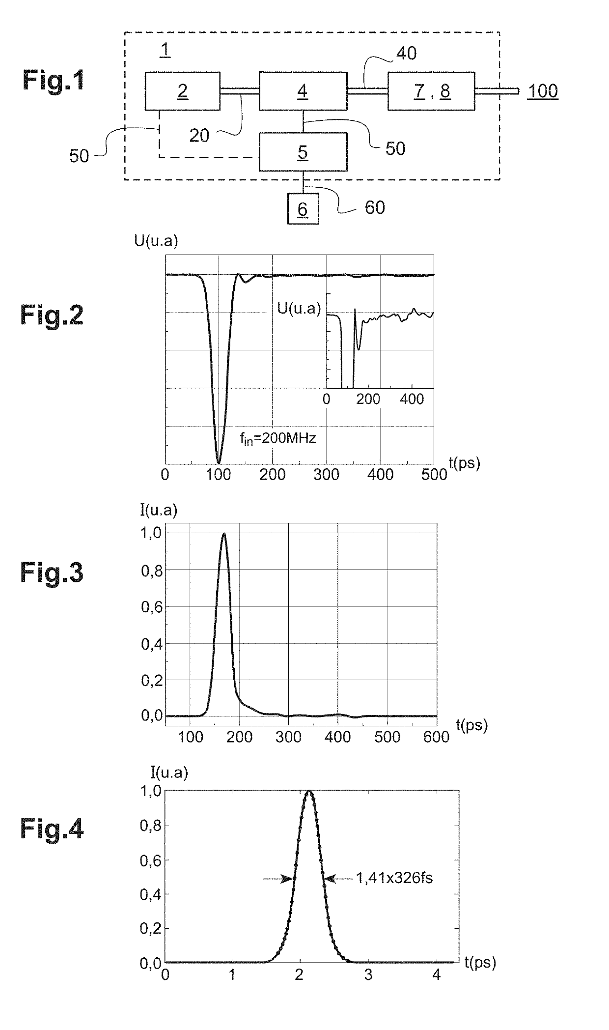
[0047]FIG. 1 schematically shows a system for generating short or ultra-short light pulses according to an embodiment;

[0048]FIG. 2 shows an example of an analog electrical modulation signal comprising an electrical pulse, this analog electrical modulation signal being generated by the power generator;

[0049]FIG. 3 shows an example of modulated light radiation generated at the exit of an electro-optical modulator to which is applied the analog electrical modulation signal of FIG. 2;

[0050]FIG. 4 shows an example of ultra-short light pulse obtained after compression of the modulated light radiation of FIG. 3;

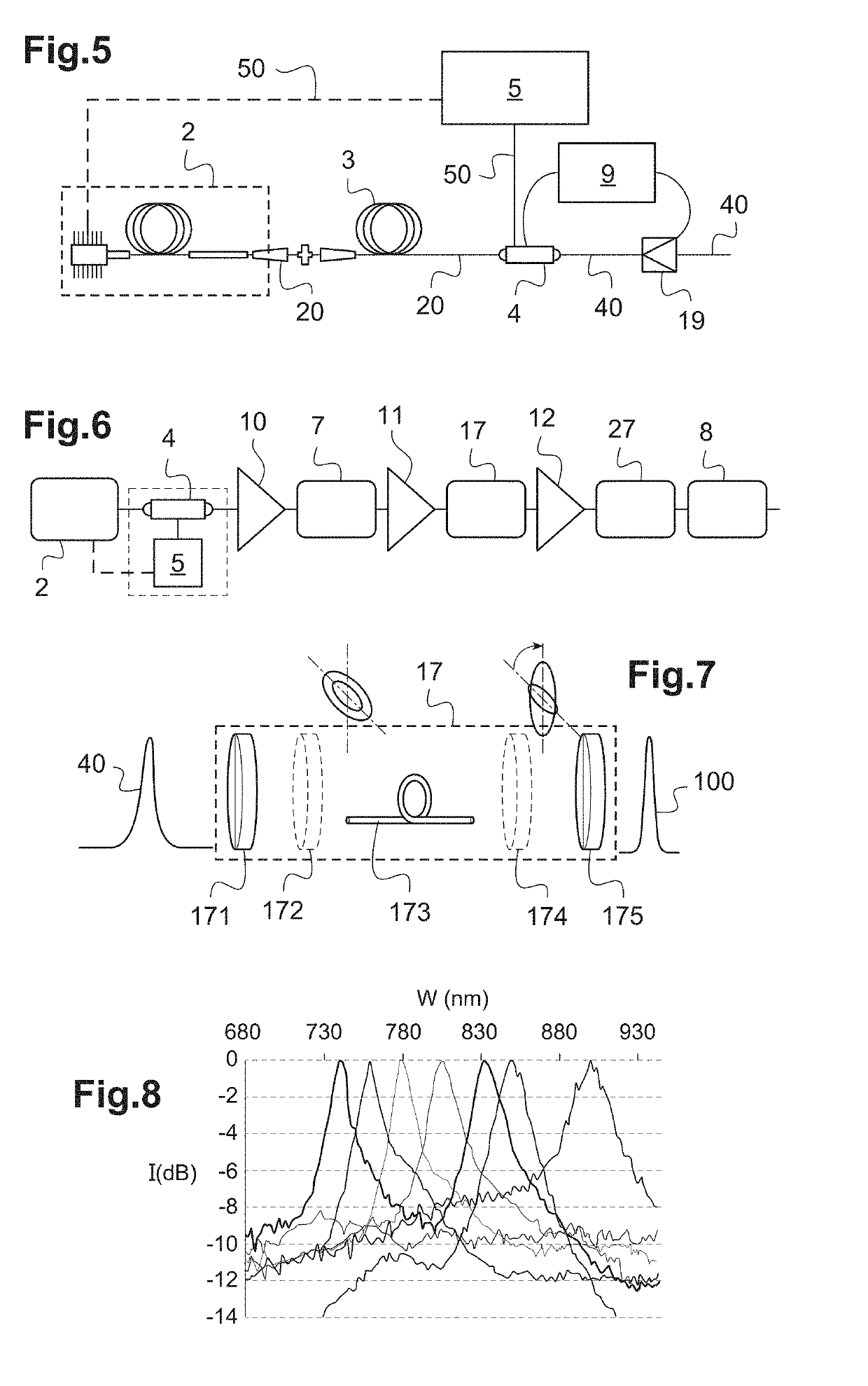
[0051]FIG. 5 schematically shows a variant of the light pulse generating system with a feedback loop;

[0052]FIG. 6 schematically shows differen...


PUM


Abstract

Disclosed is a system for generating short or ultra-short light pulses, including a light source configured to emit temporally continuous-wave light radiation, an electrical generator configured to operate at a tunable frequency in a passband included between 5 and 100 GHz and to emit an analogue modulating electrical signal including at least one electrical pulse of duration included between 10 ps and 100 ps, and an electro-optical modulator having electrodes and an electrical passband that are suitable for receiving the analog modulating electrical signal, the electro-optical modulator being configured to optically amplitude modulate the continuous-wave light radiation depending of the analog modulating electrical signal and to generate modulated light radiation including at least one light pulse of duration included between 10 ps and 100 ps.

Description

TECHNICAL FIELD TO WHICH THE INVENTION RELATES[0001]The present invention generally relates to the field of light pulse generating systems and lasers.[0002]It more particularly relates to a system and a method for generating short or ultra-short light pulses, these light pulses being tunable in rate or repetition frequency.[0003]It relates in particular to a system and a method for generating ultra-short light pulses being moreover tunable in duration and / or in wavelength.TECHNOLOGICAL BACK-GROUND[0004]The use of short to ultra-short light pulses find many applications in the scientific, industrial or medical fields. In the present document, it is meant by short light pulse, a light pulse having a duration comprised between several picoseconds and a few picoseconds. It is meant by ultra-short light pulse, a light pulse having a duration comprised between about one femtosecond (fs) and about ten picoseconds (ps). In the present document, the terms repetition frequencies and rate are ...

Claims


Application Information

Patent Timeline
IPC IPC(8): G02F1/225H01S3/00H01S3/067H01S3/23H01S5/062
CPCG02F1/2252H01S3/0057H01S3/0085H01S3/0092H01S3/06758H01S3/2375H01S5/06226G02F2203/26G02F2203/54G02F1/225H01S3/10046
Inventor ROYON, ROMAINDUBRASQUET, ROMAIN
Owner IRISIOME
Why Eureka
Try Eureka