
Integrally suppressed handgun

a suppressed and handgun technology, applied in the field of firearms, can solve the problems of uncharacteristic in dimensions and appearance of a more conventional pistol, affecting the balance, aiming, and the design of the suppressed pistol may be difficult to disassemble for maintenance and cleaning of the silencer and/or firearm components, and achieve the effect of facilitating aiming and holstering, and reducing the size of the pistol

Active Publication Date: 2019-08-08
STURM RUGER & CO INC
View PDF0 Cites 4 Cited by
  • Summary
  • Abstract
  • Description
  • Claims
  • Application Information

AI Technical Summary

Benefits of technology

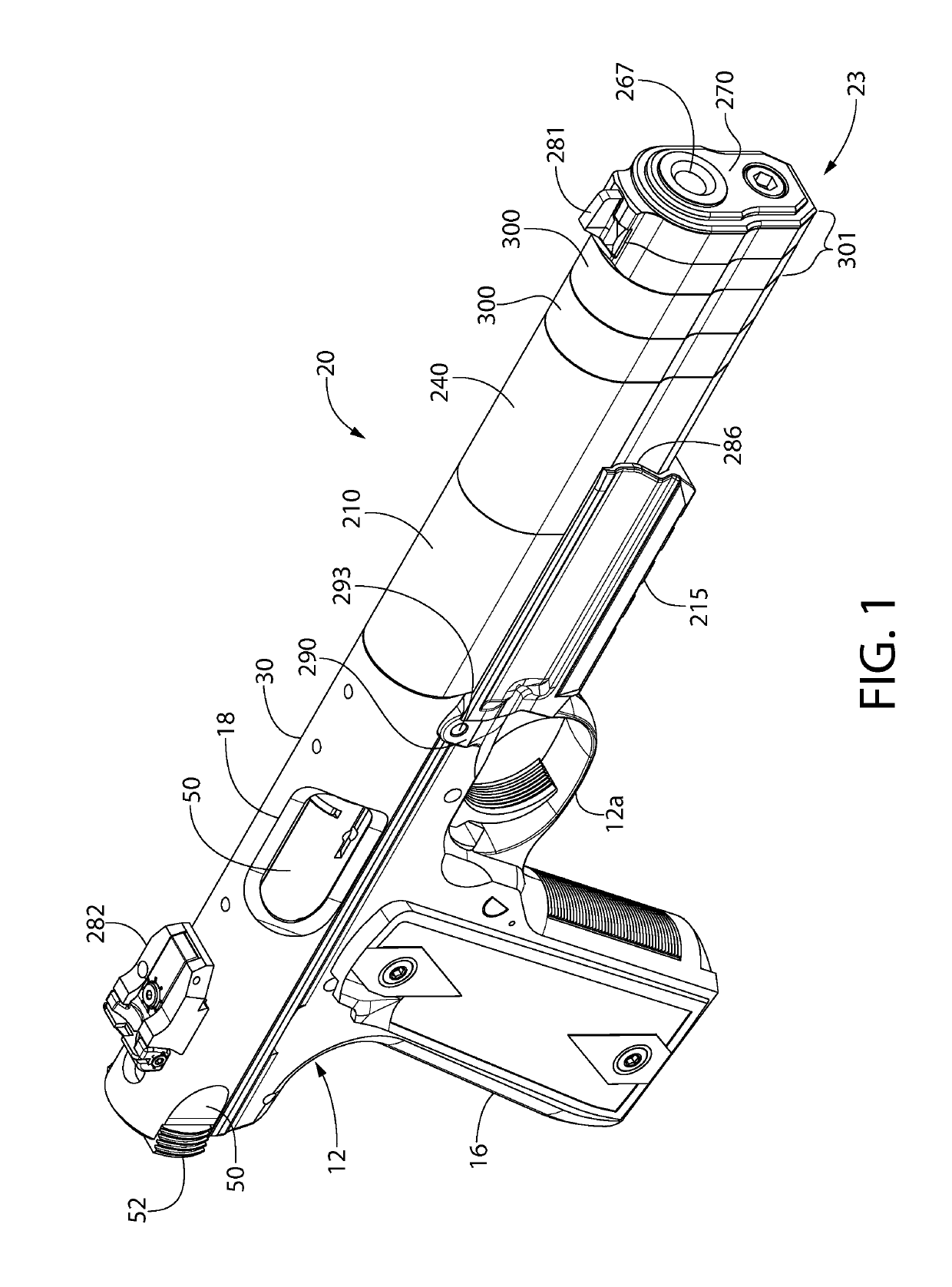
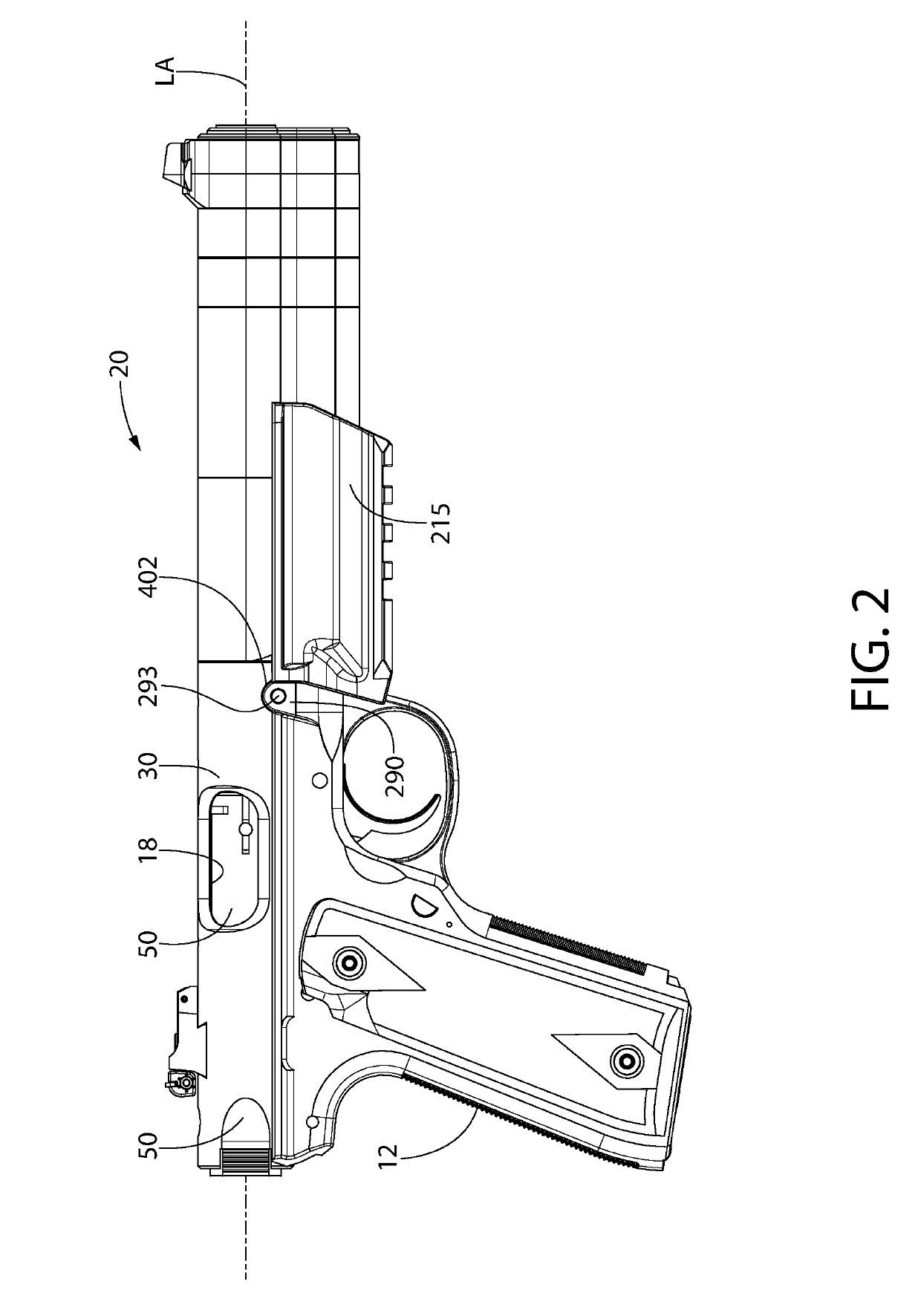
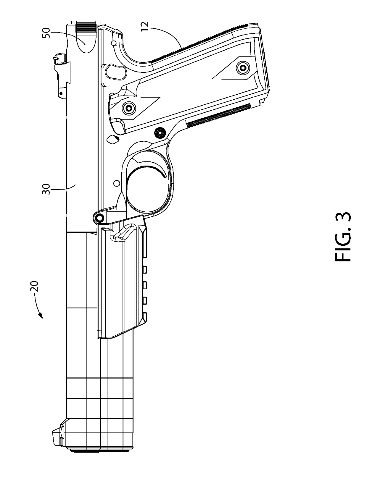
The present invention provides an integrally suppressed handgun that overcomes the shortcomings of previous designs. The handgun has a slim profile and is easy to aim and carry. The suppressor design is compact and can be easily maintained and cleaned. The front suppressor portion of the firearm has a baffled design that allows for easy assembly and disassembly for maintenance. The suppressor components have a stack of sound suppression baffles that provide improved sound suppression performance while minimizing the length of the silencer compared to conventional designs. The suppressor is length-configurable without the need for additional components. The handgun can be easily converted to an integrally suppressed firearm by the user or end user and can switch between unsuppressed and integrally suppressed firing platforms quickly and easily.

Problems solved by technology

Although some attempts have been made to integrate silencers into handguns such as a pistol, the end result is that these units may tend to be long, bulky, and cumbersome to handle.
In addition, these designs may be difficult to disassemble for maintenance and cleaning of the silencer and / or firearm components.
Accordingly, such prior integrated silencer designs may adversely affect the balance, aiming, and desired slim profile of the barrel creating a suppressed pistol uncharacteristic in dimensions and appearance from a more conventional pistol.

Method used


Image

  • Integrally suppressed handgun
  • Integrally suppressed handgun
  • Integrally suppressed handgun

Examples


Embodiment Construction

[0063]The features and benefits of the invention are illustrated and described herein by reference to exemplary (i.e. “example”) embodiments. This description of exemplary embodiments is intended to be read in connection with the accompanying drawings, which are to be considered part of the entire written description. In the description of embodiments disclosed herein, any reference to direction or orientation is merely intended for convenience of description and is not intended in any way to limit the scope of the present invention. Relative terms such as “lower,”“upper,”“horizontal,”“vertical,”, “above,”“below,”“up,”“down,”“top” and “bottom” as well as derivative thereof (e.g., “horizontally,”“downwardly,”“upwardly,” etc.) should be construed to refer to the orientation as then described or as shown in the drawing under discussion. These relative terms are for convenience of description only and do not require that the apparatus be constructed or operated in a particular orientati...


PUM


Abstract

An integrally suppressed firearm in one embodiment includes a rear firing portion defining an axial projectile bore and front suppressor portion. The suppressor portion includes a longitudinal stack of sound suppression baffles each defining a gas expansion chamber in fluid communication with the projectile bore. A mounting rod extends rearward from a front end cap of the suppressor portion and threadably engages a mounting adapter that removably couples the suppressor portion to the firing portion. A muzzle cap disposed inside a rearmost baffle removably couples the mounting adapter to the firing portion. When tightened, the rod axially compresses the baffle stack and forms a combustion gas tight enclosure without need for an additional external pressure retention tube or sleeve. The baffles are configured to form a press-fit frictional interlock with each other such that the baffle stack is self-supporting. An optional accessory rail may be coupled to the adapter.

Description

CROSS-REFERENCE TO RELATED APPLICATIONS[0001]The present application claims the benefit of U.S. Provisional Application No. 62 / 626,450 filed Feb. 5, 2018; the entirety of which is incorporated herein by reference.BACKGROUND OF THE DISCLOSURE[0002]The present disclosure generally relates to firearms, and more particularly to firearms in the form of handguns with integral silencers or suppressors that reduce muzzle noise or blast produced by discharging the firearm.[0003]Silencers or suppressors generally comprise multiple combustion gas expansion chambers in which the high pressure gas is allowed to partially expand prior to leaving the firearm. The projectile such as a bullet is propelled through the barrel of the firearm and silencer by the combustion gas. In an unsuppressed discharge firearm, the rapid expansion and depressurization of the high pressure gas at the muzzle end of the barrel produces a loud sound referred to as muzzle blast or noise. The partial pre-expansion of gas ...

Claims


Application Information

Patent Timeline
IPC IPC(8): F41A21/30F41A21/28
CPCF41A21/30F41A21/28F41A11/00F41A21/325
Inventor BARRETT, JONATHAN
Owner STURM RUGER & CO INC
Learn More