Aircraft Airflow Sensor Probe and Process of Implementing an Aircraft Sensor Probe

a sensor probe and airflow technology, applied in the direction of fluid speed measurement, instruments, transportation and packaging, etc., can solve the problems of mechanical damping systems, inability to modify damping operation based on ambient conditions and/or aircraft configurations, and voids in airflow, so as to reduce voids and adjust damping functions.

Active Publication Date: 2019-08-08
AEROSONIC LLC
View PDF0 Cites 16 Cited by
  • Summary
  • Abstract
  • Description
  • Claims
  • Application Information

AI Technical Summary

Benefits of technology

[0006]The foregoing needs are met, to a great extent, by the disclosure, wherein in one aspect a technique and apparatus are provided for an aircraft airflow sensor probe that is more accurate, less susceptible to airflow conditions that generate flutter, can adjust damping functionality, and the like.

Problems solved by technology

However, it is been found that the movement of the vane within the airflow may be subjected to flutter or other airflow conditions that move or perturb the vane and prevent accurate airflow measurements.
However, such mechanical damping systems do not include any ability to adjust damping functionality and thus cannot modify damping operation based on ambient conditions and / or aircraft configurations.
Moreover, the mechanical damping systems may be subjected to large changes in temperature (−100° F.-100° F.) during a flight of an aircraft that undesirably change damping functionality.

Method used


Image

  • Aircraft Airflow Sensor Probe and Process of Implementing an Aircraft Sensor Probe
  • Aircraft Airflow Sensor Probe and Process of Implementing an Aircraft Sensor Probe
  • Aircraft Airflow Sensor Probe and Process of Implementing an Aircraft Sensor Probe

Examples


Embodiment Construction

[0028]The disclosure will now be described with reference to the drawing figures, in which like reference numerals refer to like parts throughout. Aspects of the disclosure advantageously provide an aircraft airflow sensor probe that is more accurate, less susceptible to airflow conditions that generate flutter, can adjust damping functionality, and the like.

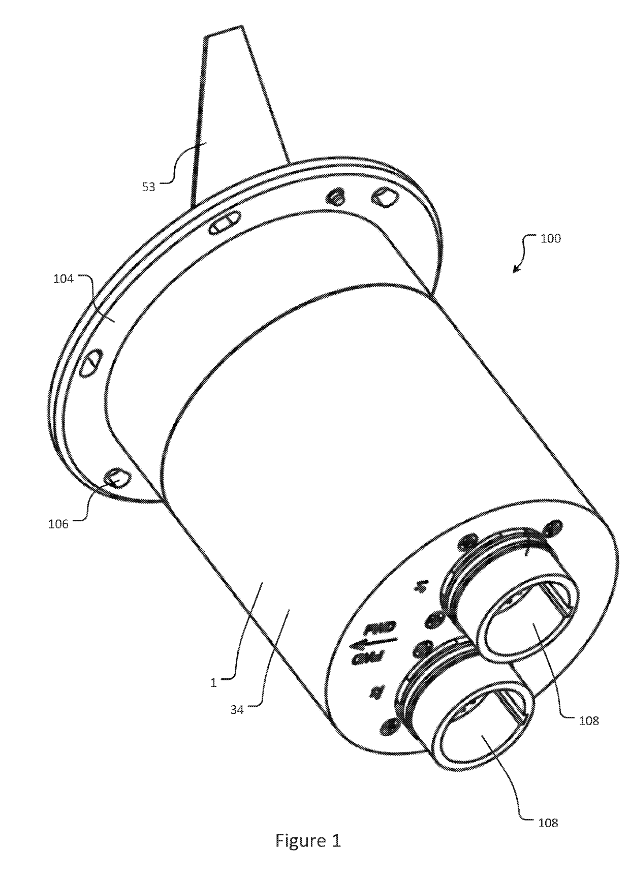
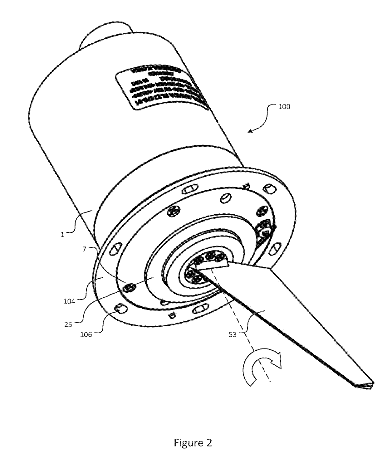
[0029]FIG. 1 illustrates a backside perspective view an aircraft airflow sensor probe according to the disclosure; and FIG. 2 illustrates a front side perspective view of the aircraft airflow sensor probe according to FIG. 1.

[0030]In particular, FIG. 1 and FIG. 2 illustrate an aircraft airflow sensor probe 100 configured as an angle of attack sensor to provide normalized angle of attack (AOA) information for flight control systems. In one aspect, the aircraft airflow sensor probe 100 may be configured as a Stall Warning Transmitter (SWT) to provide stall protection functionality for flight control systems. In some aspects, the S...


PUM


Abstract

An aircraft airflow sensor probe includes an airflow assembly or a cone assembly configured to sense a direction of local airflow outside an aircraft; a shaft configured to rotatably hold the assembly and allow rotational movement of the assembly; and a motor connected to the shaft and configured to generate a torque to damp the rotational movement of the shaft as well as the assembly. The sensor probe further includes an angle of attack processor configured to control the motor to generate the torque to damp the rotational movement of the shaft as well as the assembly and a sensor configured to sense a position of the assembly and provide the position of the assembly to the angle of attack processor. An aircraft airflow sensor process is disclosed as well.

Description

CROSS REFERENCE TO PRIOR APPLICATIONS[0001]This application claims the benefit of U.S. Provisional Application No. 62 / 627,259 filed on Feb. 7, 2018, which is hereby incorporated by reference in its entirety for all purposes as if fully set forth herein.FIELD OF THE DISCLOSURE[0002]The disclosure relates to an aircraft airflow sensor probe and a process of implementing an aircraft sensor probe. More particularly, the disclosure relates to an aircraft airflow sensor probe and a process of implementing an aircraft sensor probe having increased accuracy.BACKGROUND OF THE DISCLOSURE[0003]In typical implementations, an aircraft airflow sensor probe determines angle of attack by sensing a direction of local airflow with a vane assembly. The aircraft airflow sensor probe is typically mounted on a fuselage of an aircraft and extends through the aircraft fuselage. The angular position of the vane of the aircraft airflow sensor probe is converted to an electrical output by an angular sensor. T...

Claims


Application Information

Patent Timeline
Patent Type & Authority Applications(United States)
IPC IPC(8): G01P13/02G01P5/16B64D45/00B64F5/60
CPCG01P13/025G01P5/16B64D45/00B64F5/60B64D2045/0085G01P5/165G01P5/06
Inventor LANG, CHARLESSCHULZ, EDGARDLARKIN, JASONTURNER, DWIGHT
Owner AEROSONIC LLC
Why Eureka
Try Eureka