Power conversion apparatus

a power conversion apparatus and power supply technology, applied in power conversion systems, electrical devices, cooling/ventilation/heating modifications, etc., can solve the problems of large overall volume of the on-board charge module, large amount of heat generated, and low power density, so as to reduce the overall volume of the power conversion apparatus, simple and reliable assembly and fixing, the effect of enhancing the heat dissipation capability of the respective components

Active Publication Date: 2019-08-08
DELTA ELECTRONICS SHANGHAI CO LTD
View PDF16 Cites 3 Cited by
  • Summary
  • Abstract
  • Description
  • Claims
  • Application Information

AI Technical Summary

Benefits of technology

[0006]It is an object of the present invention to provide a power conversion apparatus. By way of optimization of the layout of various components, it is possible to provide simple and reliable assembly and fixing, while enhancing the heat-dissipation capability of the respective components, reducing the overall volume of the power conversion apparatus and increasing the overall power density of the power conversion apparatus.
[0007]It is another object of the present invention to provide a power conversion apparatus. A power element on the mother board is fixed and adhered to the heat-dissipation surface of a housing via a heat-conducting and insulated heat-dissipation module, while the respective components are disposed between the mother board and the housing and accommodated in the accommodating grooves of the housing, the heat-dissipation surface and the accommodating grooves of the housing being thermally coupled to the coolant passage of the housing together, so that the interface thermal resistance is reduced and the assembly structure is simplified, thereby achieving the goal of reducing costs and increasing the reliability and heat-dissipation capability of the power conversion apparatus.

Problems solved by technology

When the power conversion module is operating, a large amount of heat is generated.
At present, however, the design of the power conversion module and the heat dissipation design correspondingly provided by the base housing are not good, resulting in a large overall volume of the on board charge module and a low power density.
Therefore, one problem in the field that needs to be settled urgently is how to develop a power conversion apparatus to solve the problems in the prior art.

Method used


Image

  • Power conversion apparatus
  • Power conversion apparatus
  • Power conversion apparatus

Examples


Embodiment Construction

[0015]Some typical embodiments that embody the features and advantages of the present invention will be described in detail in the following paragraphs. It will be appreciated that the present invention can have various changes in various aspects, none of which deviate from the scope of the present invention, and the descriptions and figures therein are substantially used for illustration and not for limiting the present invention.

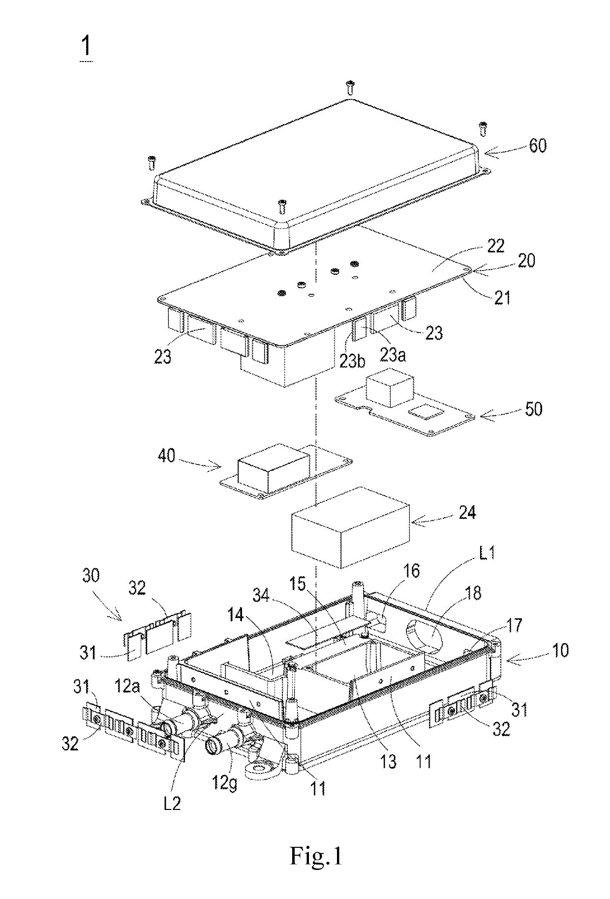
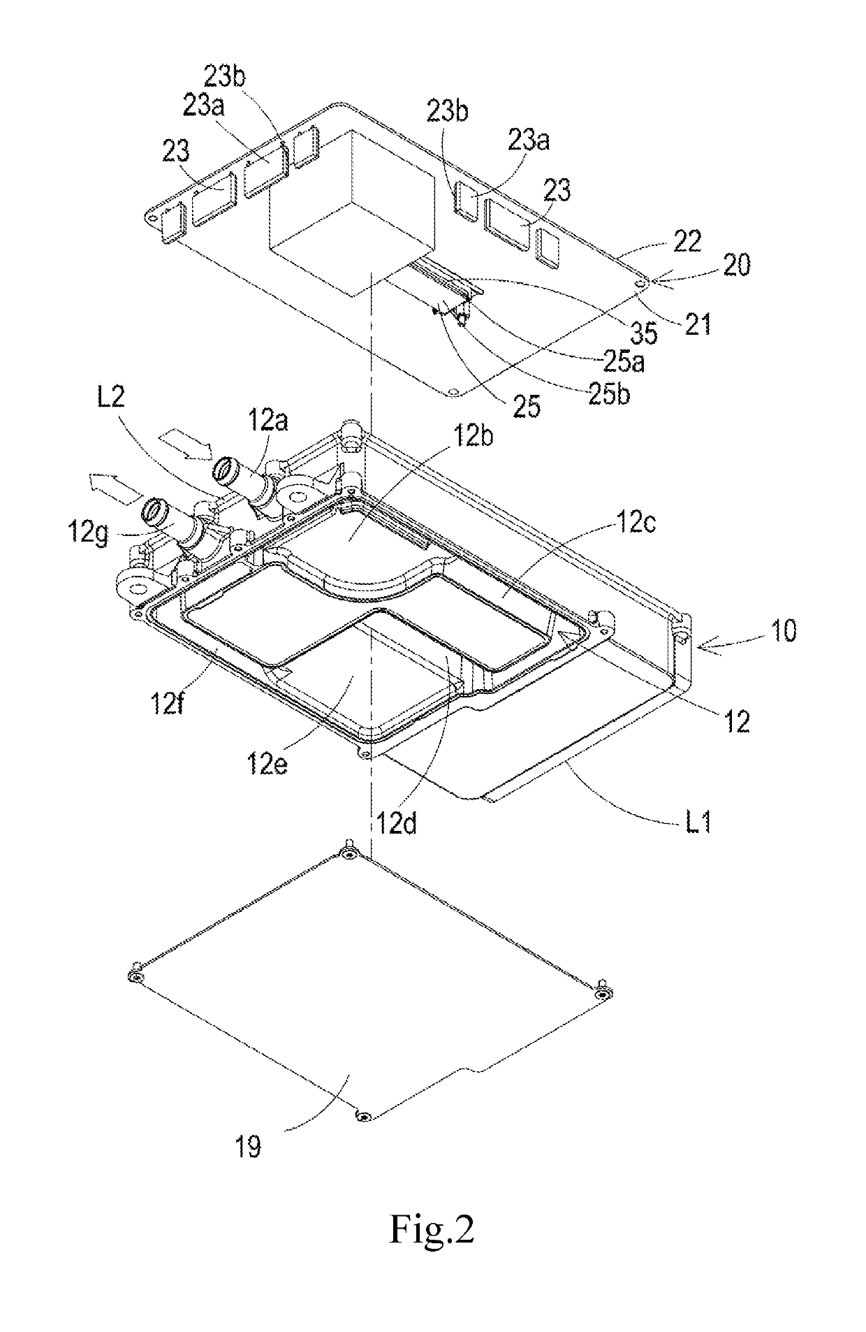
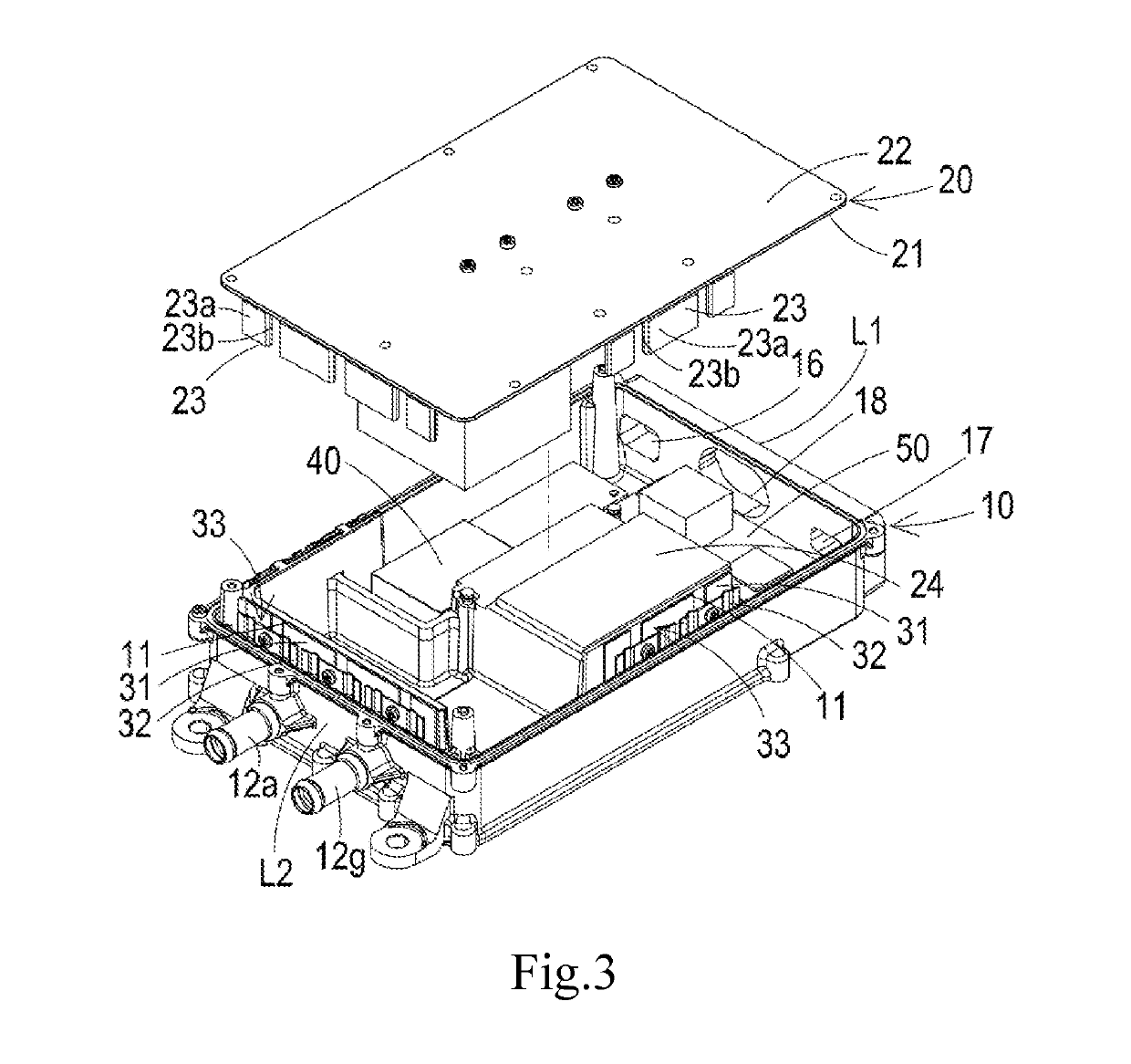
[0016]FIG. 1 is an exploded view illustrating the structure of a power conversion apparatus according to a first preferred embodiment of the present invention. FIG. 2 is an exploded view illustrating a part of the structure of the power conversion apparatus according to the first preferred embodiment of the present invention. FIG. 3 is an exploded view illustrating a part of the structure of the power conversion apparatus according to the first preferred embodiment of the present invention from another perspective. As shown in FIGS. 1 to 3, the power conve...


PUM


Abstract

A power conversion apparatus is provided, which comprises a housing, a mother board, an electromagnetic filter board, a signal board, and a heat-dissipation module. The housing includes a first heat-dissipation wall and a coolant passage. The mother board is disposed upon the housing, and comprises a first surface facing the housing and a first power device. The heat-dissipation module includes a first insulated heat-conducting sheet adhered to the corresponding first heat-dissipation wall and a first elastic clamp. When the first surface of the mother board approaches the housing to clamp the first power device within the accommodating space, the first power device is pressed against by the first elastic clamp and thus adhered to the first insulated heat-conducting sheet, so that the first power device is thermally coupled to the first heat-dissipation wall and the coolant passage via the first insulated heat-conducting sheet.

Description

CROSS-REFERENCE TO RELATED APPLICATIONS[0001]This non-provisional application claims priority under 35 U.S.C. § 119(a) on Patent Application No. 201810118950.2 filed in P.R. China on Feb. 6, 2018, the entire contents of which are hereby incorporated by reference.[0002]Some references, if any, which may include patents, patent applications and various publications, may be cited and discussed in the description of this invention. The citation and / or discussion of such references, if any, is provided merely to clarify the description of the present invention and is not an admission that any such reference is “prior art” to the invention described herein. All references listed, cited and / or discussed in this specification are incorporated herein by reference in their entireties and to the same extent as if each reference was individually incorporated by reference.TECHNICAL FIELD[0003]The present invention relates to a power supply unit, and particularly to a power conversion apparatus w...

Claims


Application Information

Patent Timeline
Patent Type & Authority Applications(United States)
IPC IPC(8): H02M1/32H05K7/20
CPCH02M1/32H05K7/20327H05K7/20381H05K7/20272H02M2001/327H02M7/003H05K7/20927H02M1/327
Inventor YOU, PEIAISUN, HAOZHANG, JINFA
Owner DELTA ELECTRONICS SHANGHAI CO LTD
Why Eureka
Try Eureka