Magnetic member for magnetic refrigerator
- Summary
- Abstract
- Description
- Claims
- Application Information
AI Technical Summary
Benefits of technology
Problems solved by technology
Method used
Image
Examples
embodiments
First Embodiment
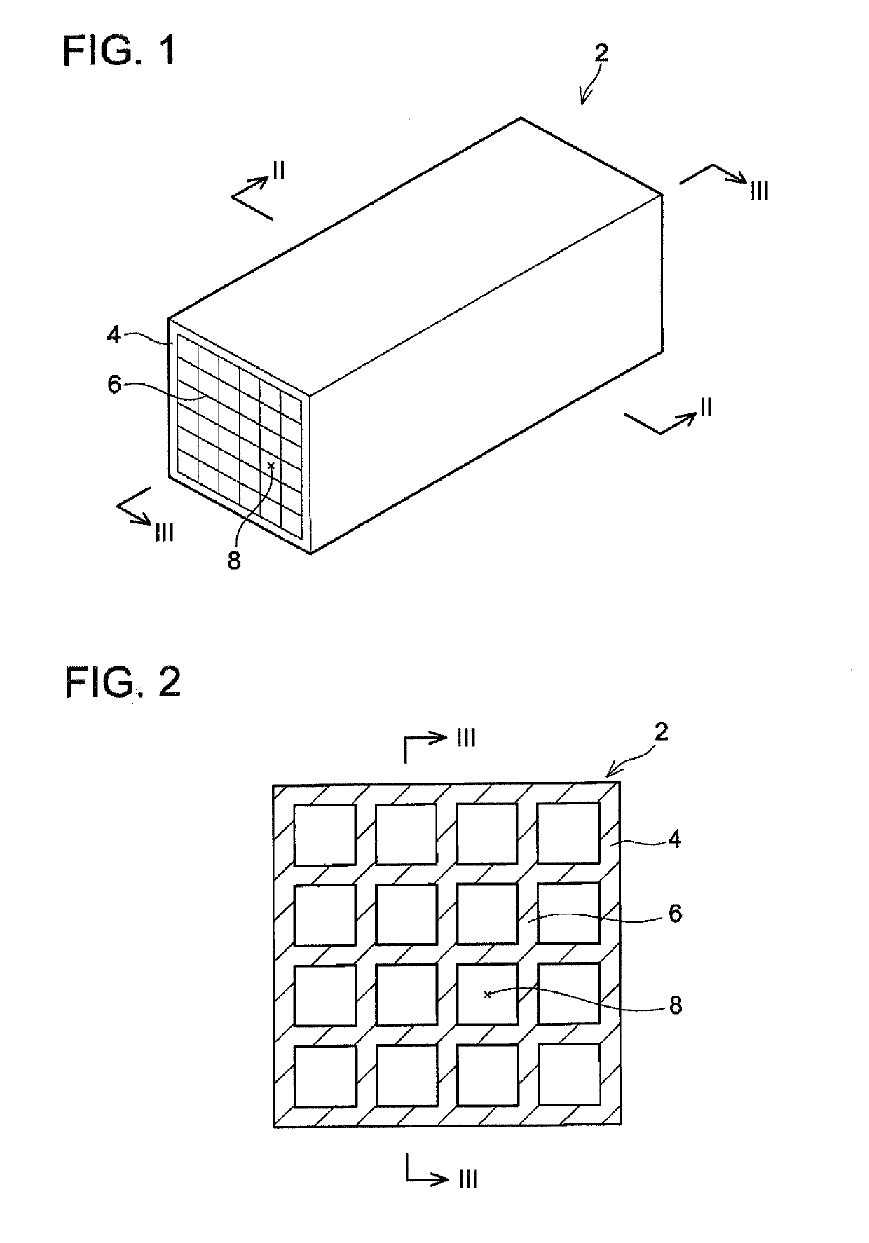
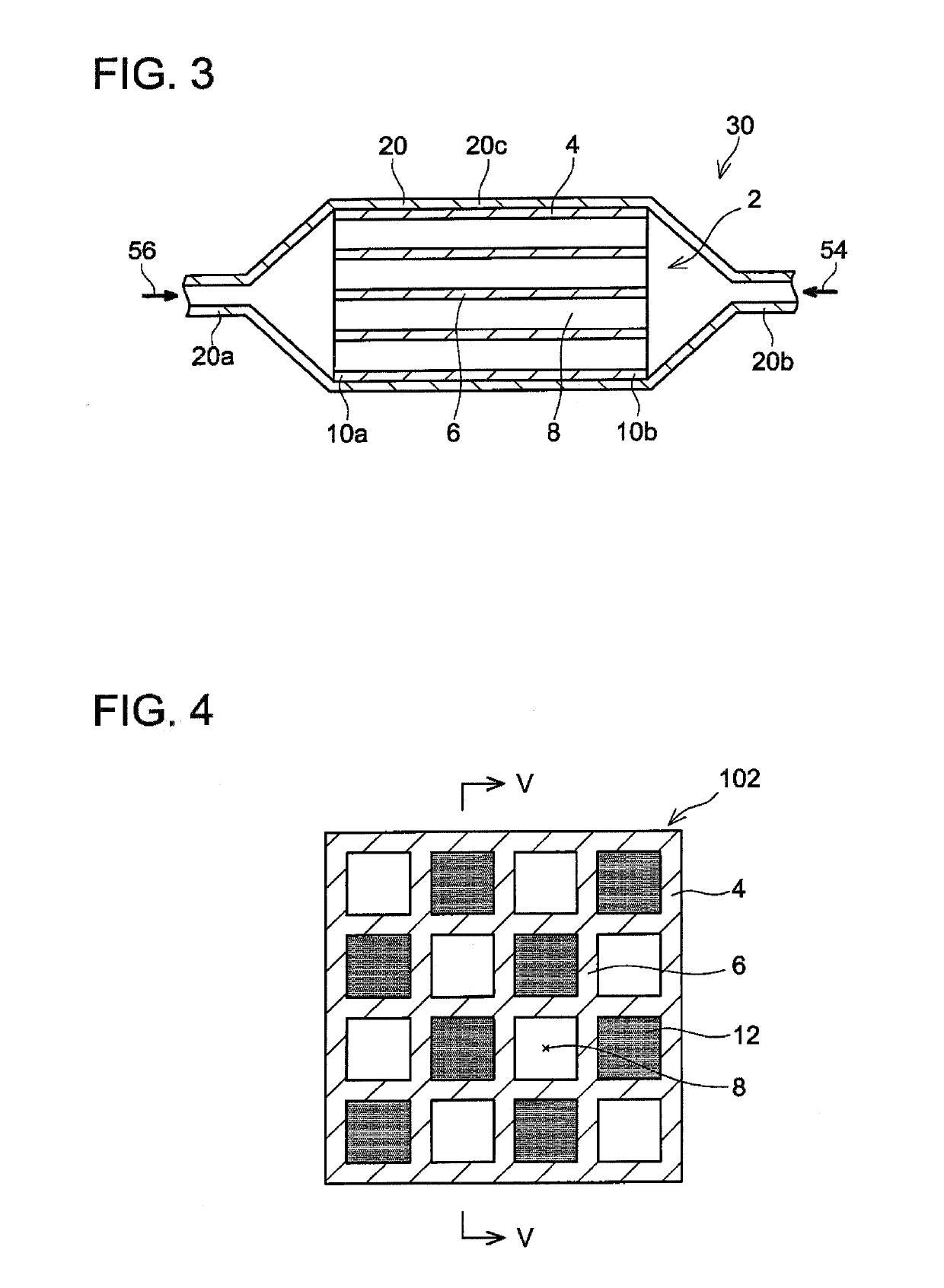
[0027]A magnetic member 2 and a refrigerator 30 will be described with reference to FIGS. 1 to 3. As shown in FIGS. 1 and 2, the magnetic member 2 has a shape of rectangular column and includes an outer layer 4 and a wall body 6. The wall body 6 extends along an axial direction of the magnetic member 2 (the outer layer 4) inside the outer layer 4. The wall body 6 defines a plurality of passages 8. The passages 8 extend from one end of the magnetic member 2 to another end thereof. That is, the passages 8 are exposed at both end faces of the magnetic member 2 in the axial direction (FIGS. 1 and 2 show one of the end faces). The magnetic member 2 includes a honeycomb structure. The magnetic member 2 is manufactured by extrusion-molding a mixture of La (Fe, Si)13 compound particles having magnetocaloric effect and glass powder functioning as an inorganic binder. The outer layer 4 and the wall body 6 are integrally molded and are constituted of a same material.
[0028]Here,...
second embodiment
[0034]A magnetic member 102 will be described with reference to FIGS. 4 and 5. The magnetic member 102 can be used in the refrigerator 30 (see FIG. 3) in place of the magnetic member 2. The magnetic member 102 is a variant of the magnetic member 2. For configurations of the magnetic member 102 that are the same as those of the magnetic member 2, the same reference signs are assigned and explanation thereof may be omitted.
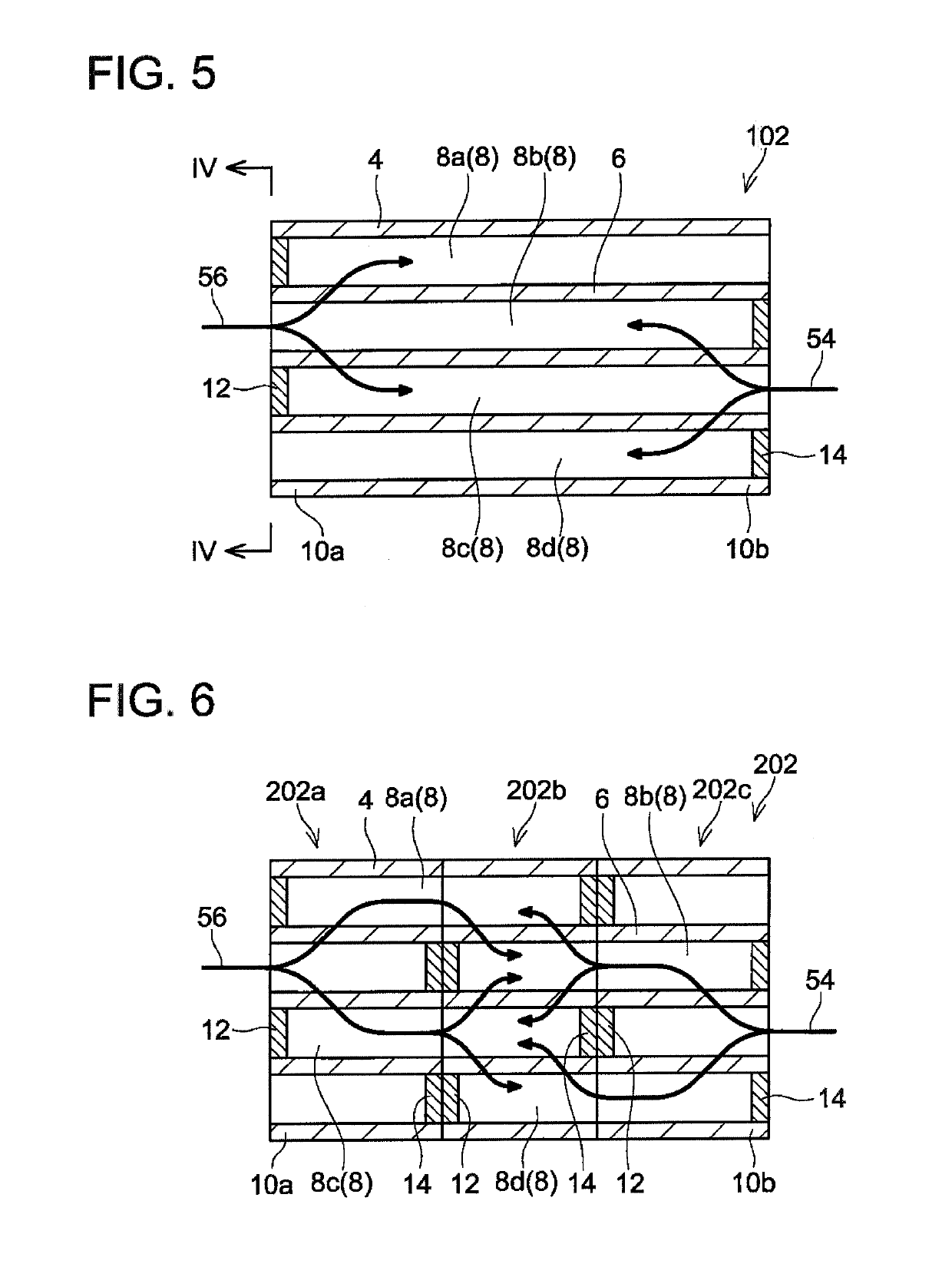
[0035]In the magnetic member 102, one end of each passage 8 in the axial direction is blocked by a sealing body 12 or 14. Specifically, a part of the first end 10a of the magnetic member 102 is blocked by the first sealing bodies 12, and a part of the second end 10b is blocked by the second sealing bodies 14. As shown by passages 8a, 8b, the second sealing body 14 is provided in the passage 8 (the passage 8b) that is adjacent to the passage 8 (the passage 8a) in which the first sealing body 12 is provided. That is, the first sealing body 12 is not provided in the pa...
third embodiment
[0037]With reference to FIG. 6, a magnetic member 202 will be described. The magnetic member 202 can also be used in the refrigerator 30 (see FIG. 3) in place of the magnetic member 2. The magnetic member 202 is a variant of the magnetic member 102. For configurations of the magnetic member 202 that are the same as those of the magnetic member 102, the same reference signs are assigned and explanation thereof may be omitted.
[0038]The magnetic member 202 includes a first partial magnetic member 202a, a second partial magnetic member 202b and a third partial magnetic member 202c, A structure of each of the partial magnetic members 202a, 202b and 202c is substantially the same as that of the magnetic member 102. The partial magnetic members 202a, 202b and 202c are constituted of materials having different magnetic transition temperatures from one another. The first partial magnetic member 202a including the first end 10a is constituted of a material having the highest magnetic transiti...
PUM
| Property | Measurement | Unit |
|---|---|---|
| Magnetocaloric effect | aaaaa | aaaaa |
| Transition temperature | aaaaa | aaaaa |
Abstract
Description
Claims
Application Information
 - R&D
- Intellectual Property
- Life Sciences
- Materials
- Tech Scout
- Unparalleled Data Quality
- Higher Quality Content
- 60% Fewer Hallucinations
Browse by: Latest US Patents, China's latest patents, Technical Efficacy Thesaurus, Application Domain, Technology Topic, Popular Technical Reports.
© 2025 PatSnap. All rights reserved.Legal|Privacy policy|Modern Slavery Act Transparency Statement|Sitemap|About US| Contact US: help@patsnap.com


