Method for increasing the accuracy of traffic cameras using optical masking technology

a technology of optical masking and traffic cameras, applied in the field of methods and devices for increasing the accuracy of traffic cameras, can solve the problems of undesirable phenomenon, affecting the safety of citizens, and traffic signal lights that may remain red longer than desired, and achieve the effect of reducing the aperture of the iris

Active Publication Date: 2019-08-15
ITS PLUS INC
View PDF8 Cites 4 Cited by
  • Summary
  • Abstract
  • Description
  • Claims
  • Application Information

AI Technical Summary

Benefits of technology

[0010]The illustrative embodiments also provide for a method of managing traffic flow. The method includes receiving, at a camera having an iris, an image containing vehicle traffic flow. The method also includes processing, using a processor, the image to mask areas in the image that exceed a predetermined number of candelas. The method also includes after processing, determining whether an area in the areas remains above the predetermined number of candelas. The method also includes, only after determining that the area remains above the predetermined number of candelas, reducing an aperture of the iris until the area is below the predetermined number of candelas. The method also includes thereafter analyzing, using the processor, the image to determine a parameter related to the vehicles, whereby an analysis is performed. The method also includes managing the traffic flow based on the analysis.

Problems solved by technology

As a result, the traffic signal light might stay red for longer than desired, possibly indefinitely.
As a result, a public safety hazard may be created.
This phenomenon is undesirable.
Additionally, bright lights in the field of view of the camera can cause vehicles to be missed.
Direct sunlight and glare during sunrise and sunset often cause a vehicle detection algorithm to become less effective; sometimes to the point of completely missing a vehicle approaching a stoplight, which is also undesirable.

Method used


Image

  • Method for increasing the accuracy of traffic cameras using optical masking technology
  • Method for increasing the accuracy of traffic cameras using optical masking technology
  • Method for increasing the accuracy of traffic cameras using optical masking technology

Examples


Embodiment Construction

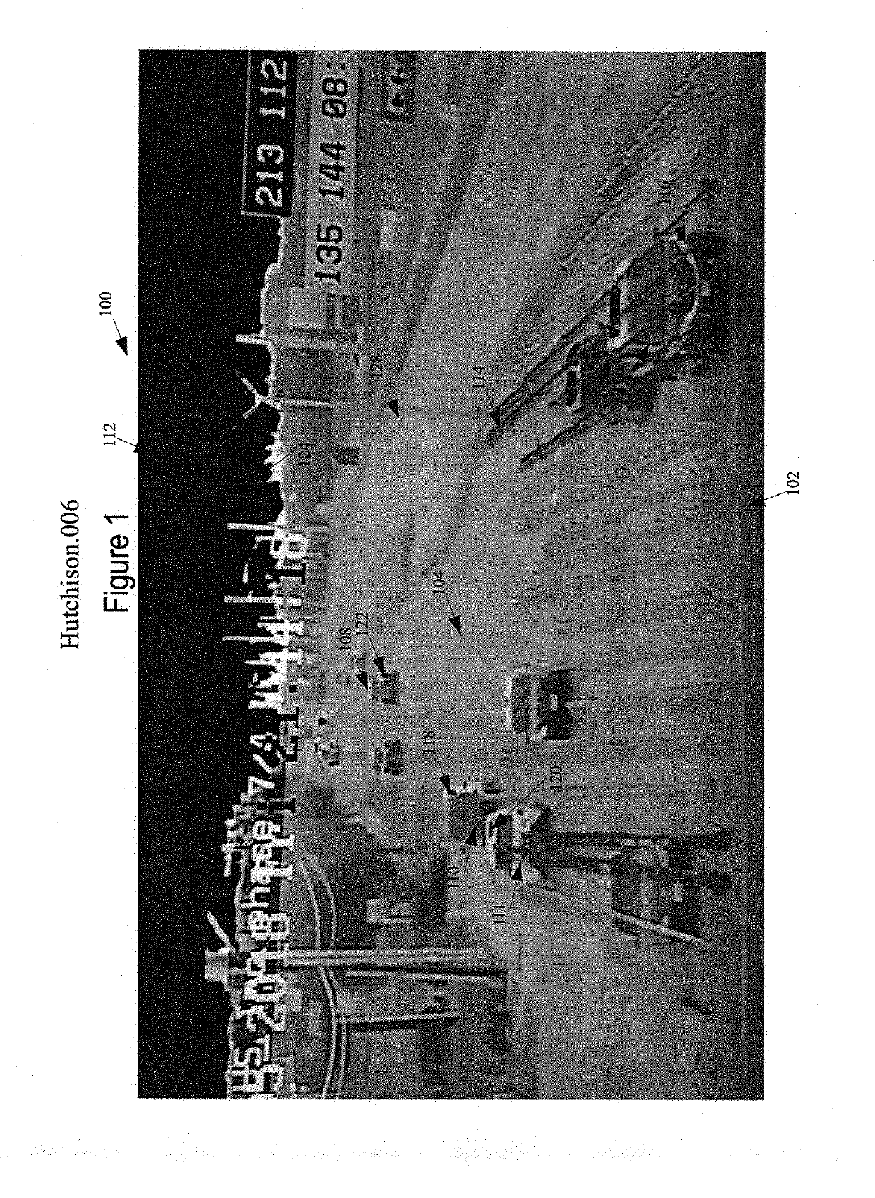
[0017]Unless otherwise provided, as used herein, the term “vehicle” refers to any kind of vehicle which may be subject to traffic signals. Thus, for surface roads, the term “vehicle” refers to automobiles (cars and trucks), commercial trucks and other commercial vehicles, motorcycles, bicycles, mopeds, tractors, and other forms of vehicles that may be required by law to obey traffic signals. For waterways, the term “vehicle” includes boats, ships, kayaks, or any other form of water vehicle that may be subject to regulation at an intersection of a waterway. For airports, taxiing aircraft may be subject to ground traffic signals, and thus are also “vehicles.” For rail road systems, the term “vehicle” includes trains or other vehicles which may be subject to train signals. However, while the term “vehicle” by itself is broadly interpreted, the illustrative embodiments are especially applicable to motor vehicles and man powered vehicles that are subject to regulation by traffic signals ...


PUM


Abstract

A method of managing traffic flow. The method includes receiving, at a camera, an image containing vehicle traffic flow. The method also includes processing, using a processor, the image to mask areas in the image that exceed a predetermined number of candelas. The method also includes thereafter analyzing, using the processor, the image to determine a parameter related to the vehicles, whereby an analysis is performed. The method also includes managing the traffic flow based on the analysis.

Description

BACKGROUND INFORMATION1. Field:[0001]The present disclosure relates to methods and devices for increasing the accuracy of traffic cameras using masking technology.2. Background:[0002]Traffic cameras have been used by governmental and private entities to track vehicle traffic and modify the timing of traffic signals accordingly. In particular, optical-based vehicle detection systems commonly used by transportation agencies require a high degree of reliability and performance.[0003]At a traffic intersection with vehicle detection technology, a missed vehicle could sit at the intersection indefinitely. As a result, the traffic signal light might stay red for longer than desired, possibly indefinitely. Additionally, sooner or later, a vehicle will choose to run the red light which is not changing. As a result, a public safety hazard may be created. This phenomenon is undesirable.[0004]Additionally, bright lights in the field of view of the camera can cause vehicles to be missed. Bright ...

Claims


Application Information

Patent Timeline
Patent Type & Authority Applications(United States)
IPC IPC(8): G06K9/00H04N5/272G08G1/01
CPCG06K9/00785H04N5/272G08G1/01G08G1/0104G08G1/0175G08G1/0116G08G1/0145G08G1/04G08G1/015G08G1/052G08G1/08G08G1/054G06V20/54
Inventor HUTCHISON, MICHAEL COLEINGRAM, STACI MARLEA
Owner ITS PLUS INC
Why Eureka
Try Eureka