
System and Method for Transmitting and Receiving Radar Data Using the Automatic Identification System

a technology of automatic identification and transmitting radar, which is applied in the direction of waterborne vessel navigational aids, using reradiation, instruments, etc., can solve the problems of difficult detection of non-emitting targets, difficult tracking of non-emitting targets far from shore, and high cost of satellite imagery

Active Publication Date: 2019-08-15
THE UNITED STATES OF AMERICA AS REPRESENTED BY THE SECRETARY OF THE NAVY
View PDF0 Cites 8 Cited by
  • Summary
  • Abstract
  • Description
  • Claims
  • Application Information

AI Technical Summary

Benefits of technology

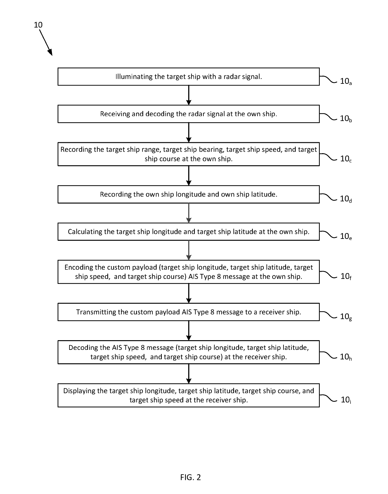
The present invention is a system that uses radar and encoder technology to track and locate target ships. The system allows the own ship to illuminate the target ship with a radar signal and record its range, bearing, speed, and course. The own ship then sends a custom payload AIS Type 8 message with this information to a receiver ship. The receiver ship decodes the message and displays the target ship's position, providing valuable navigation information. The technical effect of the invention is improved target tracking and navigation through the use of radar and encoder technology.

Problems solved by technology

Non-emitting targets are hard to track in the ocean because they do not emit radio signals which can be used to detect, locate, and track them.
Non-emitting targets far from shore are challenging to detect because they are out of range of shore-based radar systems.
Some disadvantages of using SAR satellites to detect non-emitting ships include: (1) the expense of satellite imagery; (2) that ship detection algorithms need to be developed; and (3) that the satellites orbit the Earth every few hours and thus don't have the ability to persistently loiter over and monitor a specific area.
The disadvantage of such a method however, is the expense of constantly sending data over a satellite Internet connection.

Method used


Image

  • System and Method for Transmitting and Receiving Radar Data Using the Automatic Identification System
  • System and Method for Transmitting and Receiving Radar Data Using the Automatic Identification System

Examples


Embodiment Construction

[0012]While this invention may be embodied in different forms, the drawings and this section describe in detail specific embodiments of the invention with the understanding that the present disclosure is to be considered merely a preferred embodiment of the invention, and is not intended to limit the invention in any way.

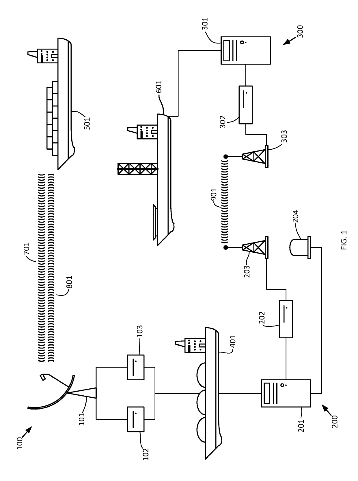
[0013]FIG. 1 depicts an embodiment of the system. FIG. 2 depicts a method 10 where a target ship 501 is tracked using an embodiment of the system. An own ship 401 uses a radar subsystem 100 comprising a radar antenna 101, radar transmitter 102, and a radar receiver 103 to detect objects such as a target ship 501. The radar transmitter 102 transmits a radar signal 701 through the radar antenna 101. Step 10a. This radar signal 701 is reflected off of the target ship 501 in the form of a return signal 801, which is received by the radar receiver 103 via the radar antenna 101. Step 10b. The return signal 801 is transmitted to and decoded at the first computer 201, which...


PUM


Abstract

A system comprising a radar subsystem including a radar transmitter and a radar receiver, and an encoder subsystem including a computer connected to a transmitter and two antennas. The computer is configured to encode and transmit a custom payload AIS Type 8 message. A second computer connected to a receiver and antenna receives the message. The custom payload AIS Type 8 message contains target longitude, latitude fields, range, and bearing fields.A method for transmitting and receiving the radar track of a target ship including: receiving the radar signal at the own ship; encoding the target ship longitude, latitude, speed, and course into a custom payload AIS Type 8 message; transmitting the custom message to a receiver ship; decoding and displaying the target ship longitude, latitude, course, and speed at the receiver ship.

Description

CROSS-REFERENCE TO RELATED APPLICATION[0001]This application claims the benefit of U.S. Provisional Patent Application Ser. No. 62 / 586,331 filed Nov. 15, 2017.FEDERALLY FUNDED RESEARCH AND DEVELOPMENT[0002]The System and Method for Transmitting and Receiving Radar Data Using the Automatic Identification System is assigned to the United States Government and is available for licensing and commercial purposes. Licensing and technical inquiries may be directed to the Office of Research and Technical Applications, Space and Naval Warfare Systems Center Pacific (Code 72120), San Diego, Calif., 92152 via telephone at (619) 553-2778 or email at ssc_pac_t2@navy.mil. Reference Navy Case 103715.BACKGROUND OF THE INVENTION[0003]This is a system and method that broadcasts the radar contacts, visible on a ship-based radar system, over Automatic Identification System (AIS) channels. This system and method allows non-emitting targets to be located and tracked using the AIS system when the targets ...

Claims


Application Information

Patent Timeline
IPC IPC(8): H04B7/185G01S13/72G01S13/93G08G3/02B63B51/00G01S13/937
CPCH04B7/18513G01S13/72G01S13/9307G08G3/02B63B51/00G01S7/003G01S13/937G01S13/86
Inventor BAGNALL, BRYAN D.MATVEYEV, VLADIMIRCHEUNG, SPARTASTASTNY, JOHN C.
Owner THE UNITED STATES OF AMERICA AS REPRESENTED BY THE SECRETARY OF THE NAVY
Learn More