Retinal imaging device and related methods

a retinal imaging and retinal technology, applied in the field of retinal imaging devices, can solve problems such as vision loss, macular degeneration, and loss of central vision, and achieve the effect of enhancing the imaging of the user's retina

Active Publication Date: 2019-08-22
NOTAL VISION
View PDF8 Cites 7 Cited by
  • Summary
  • Abstract
  • Description
  • Claims
  • Application Information

AI Technical Summary

Benefits of technology

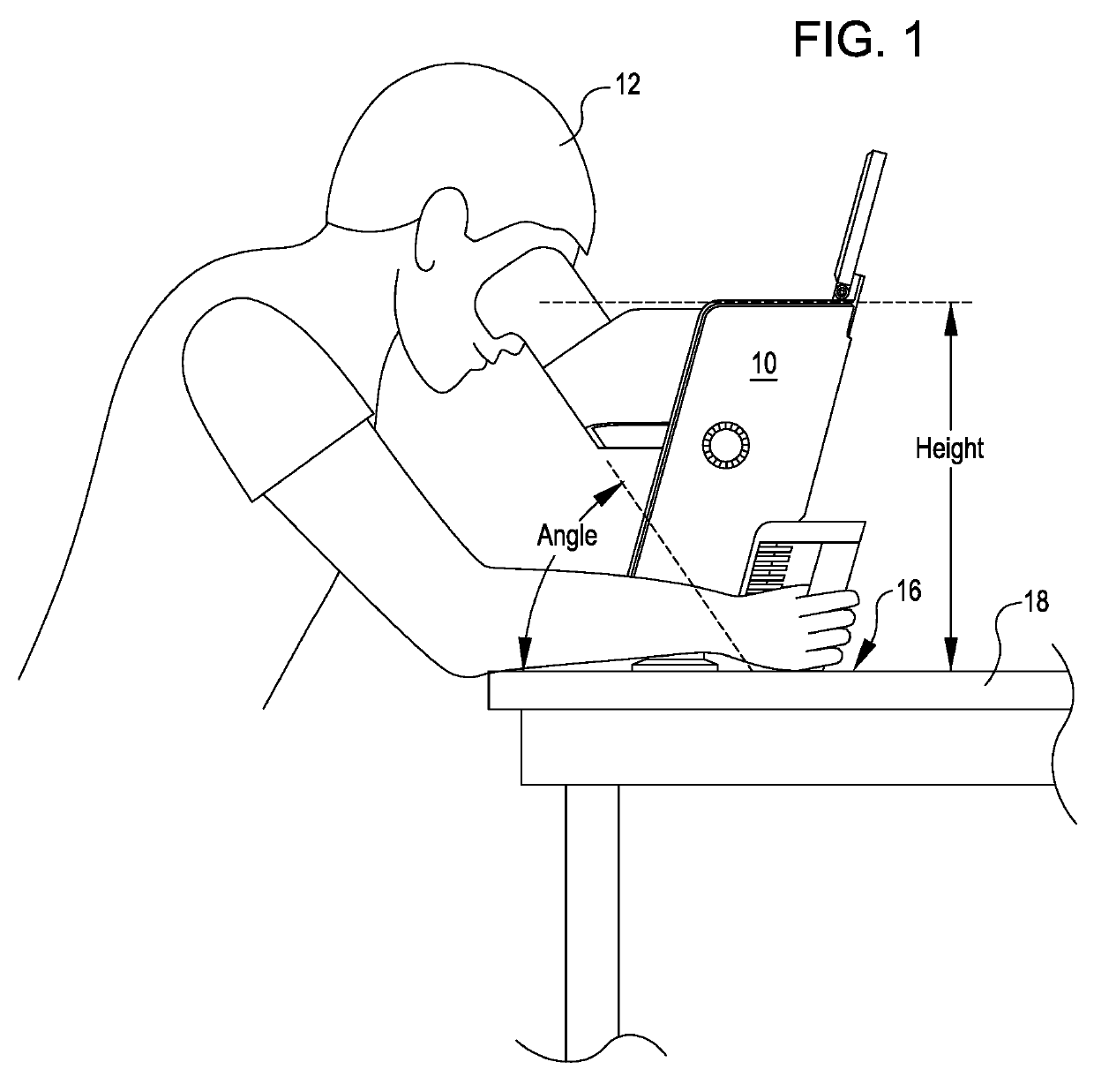
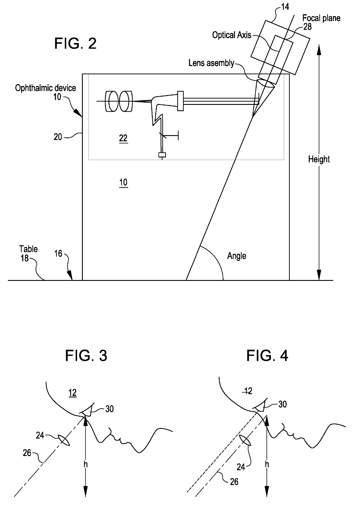
[0007]Ophthalmic imaging devices and related methods orient an optical axis of the imaging device at an angle from 45 degrees to 85 degrees from a horizontal surface on which the ophthalmic imaging device is supported and employ a viewer assembly that stabilizes the user's head in a suitable position and orientation relative to the optical axis. In many embodiments, the imaging device conducts imaging over a relatively long period of time (e.g., 30 seconds) and the user engages the user's head with the viewer assembly to stabilize the position and orientation of the user's head relative to the optical axis over the imaging period. In many embodiments, the viewer assembly accommodates different positions and / or orientations of the user's head relative to the optical axis so as to enable alignment, by the user, of one of the user's eyes with the optical axis. The combination of the optical axis being angled relative to horizontal and the configuration of the viewer assembly enables the user to self-align an eye of the user with the optical axis and maintain the position of the eye relative to the optical axis over the imaging period while sitting in a natural, comfortable position. Moreover, the combination of the optical axis being angled relative to horizontal and the configuration of the viewer assembly effectively inhibits gravity induced downward drift movement by the user during the imaging period.
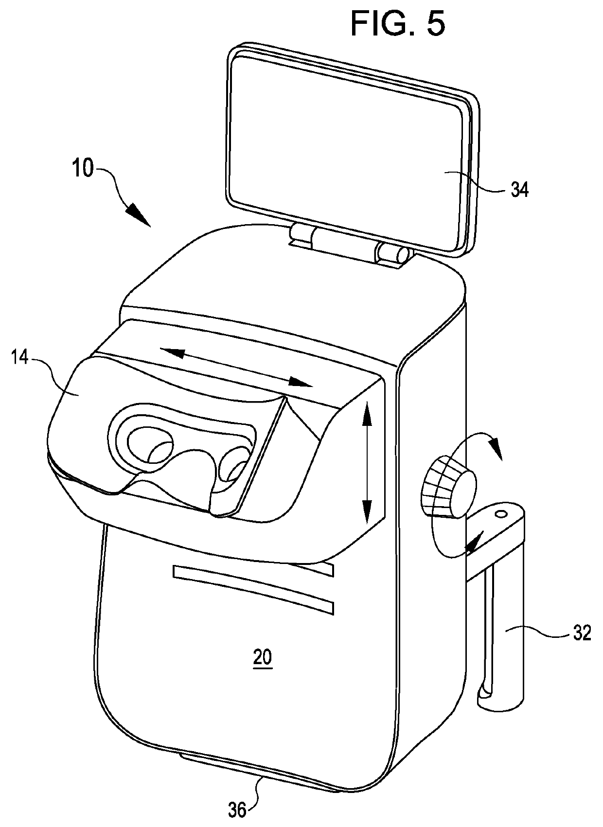
[0008]Thus, in many embodiments, an ophthalmic imaging device includes an imaging assembly having an optical axis, a housing assembly to which the imaging assembly is attached, and a viewer assembly coupled with the housing assembly. The housing assembly is configured to rest on a horizontal surface during operation of the imaging assembly. The optical axis is oriented at an angle from 45 degrees to 85 degrees from the horizontal surface when the housing assembly rests on the horizontal surface. The viewer assembly includes an interface surface shaped to engage a user's head to stabilize a position and an orientation of the user's head relative to the optical axis. The viewer assembly accommodates different positions and / or orientations of the user's head relative to the optical axis so as to enable alignment, by the user, of one of the user's eyes with the optical axis.
[0009]In many embodiments, the viewer assembly is adapted to block light when engaged by a user's head to create a dark environment to dilate the user's pupil to enhance imaging of the user's retina. For example, in some embodiments, the interface surface is configured to engage the user's head continuously along a perimeter segment that surrounds the user's eyes. In such embodiments, the perimeter segment can extend continuously from below the user's left eye, around the user's left eye between the user's left eye and the user's left ear, above the user's eyes, around the user's right eye between the user's right eye and the user's right ear, to below the user's right eye.
[0016]In many embodiments, the viewer assembly is adapted to enable a suitable range of positions and / or orientations of the user's head relative to the optical axis. For example, in many embodiments, the different positions and / or orientations of the user's head accommodated by the viewer assembly enable repositioning of the user's eye by 20 mm along any axis perpendicular to the optical axis.

Problems solved by technology

Macular degeneration is the leading cause of vision loss in the United States of America.
If macular degeneration continues to progress to advanced stages, central vision may be lost.
Existing OCT imaging systems, however, are typically expensive and may have to be operated by a trained technician.
As a result, the use of such OCT imaging systems is typically restricted to specialized eye care clinics, thereby limiting use of such OCT imaging systems for widespread screening for early stage macular degeneration.

Method used


Image

  • Retinal imaging device and related methods
  • Retinal imaging device and related methods
  • Retinal imaging device and related methods

Examples


Embodiment Construction

[0034]In the following description, various embodiments of the present invention will be described. For purposes of explanation, specific configurations and details are set forth in order to provide a thorough understanding of the embodiments. However, it will also be apparent to one skilled in the art that the present invention may be practiced without the specific details. Furthermore, well-known features may be omitted or simplified in order not to obscure the embodiment being described.

[0035]Introduction

[0036]Many patients with retinal diseases are treated with intra-ocular injection per general guidelines based on the average patient. Progression of a retinal disease in any specific patient, may progress differently than in the average patient. Moreover, the specific patient may respond differently to treatment than the average patient. Accordingly, there is a strong clinical need to monitor the progression of a retinal disease in some patients on a continual basis so that the ...


PUM


Abstract

Ophthalmic imaging devices and related methods employ self-alignment of a user with an optical axis of the imaging device. An ophthalmic imaging device includes an imaging assembly having an optical axis, a housing assembly, and a viewer assembly. The housing assembly is configured to rest on a horizontal surface during operation of the imaging assembly. The optical axis is oriented at an angle from 45 degrees to 85 degrees from the horizontal surface. The viewer assembly includes an interface surface shaped to engage a user's head to stabilize a position and an orientation of the user's head relative to the optical axis. The viewer assembly accommodates different positions and / or orientations of the user's head relative to the optical axis so as to enable alignment, by the user, of one of the user's eyes with the optical axis.

Description

CROSS REFERENCE TO RELATED APPLICATIONS[0001]The present application is a Continuation-in-Part of International Application No. PCT / IL2018 / 051174, filed Nov. 4, 2018, which claims the benefit of U.S. Provisional Application Ser. No. 62 / 582,772, filed on Nov. 7, 2017, all of which are incorporated by reference herein in their entirety for all purposes.BACKGROUND[0002]Macular degeneration is the leading cause of vision loss in the United States of America. In macular degeneration, the central portion of the retina (a.k.a., the macula) deteriorates. When healthy, the macula collects and sends highly detailed images to the brain via the optic nerve. In early stages, macular degeneration typically does not significantly affect vision. If macular degeneration progresses beyond the early stages, vision becomes wavy and / or blurred. If macular degeneration continues to progress to advanced stages, central vision may be lost.[0003]Although macular degeneration is currently considered to be in...

Claims


Application Information

Patent Timeline
Patent Type & Authority Applications(United States)
IPC IPC(8): A61B3/12A61B3/10A61B3/14
CPCA61B3/12A61B3/102A61B3/14A61B3/0008A61B3/15A61B3/152A61B3/0083A61B3/0091A61B3/0075A61B3/11A61B3/0041A61B3/08A61B3/024
Inventor RAFAELI, OMERRAPP, MUKIBENYAMINI, HANOCH GIDEONALSTER, YAIRSHARIF, EITANPASCAL, AMIT
Owner NOTAL VISION
Why Eureka
Try Eureka