Delivery device with coaxial cable, apparatus comprising said device and method

a coaxial cable and delivery device technology, applied in the field of medical devices and apparatuses, can solve the problems of greater heat dissipation and greater resistance of tissues, and achieve the effects of avoiding burns, good thermal conductors, and low electric losses

Active Publication Date: 2019-08-22
EL EN SPA
View PDF2 Cites 4 Cited by
  • Summary
  • Abstract
  • Description
  • Claims
  • Application Information

AI Technical Summary

Benefits of technology

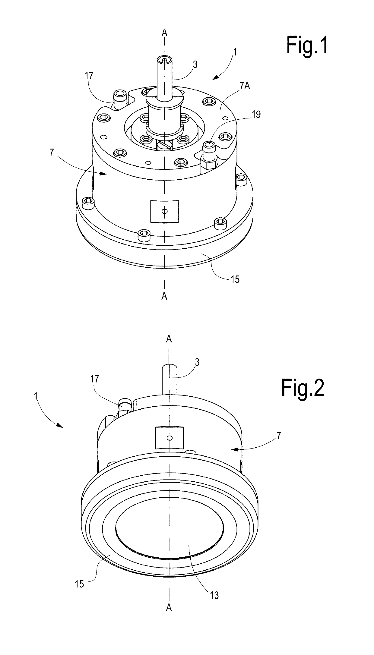
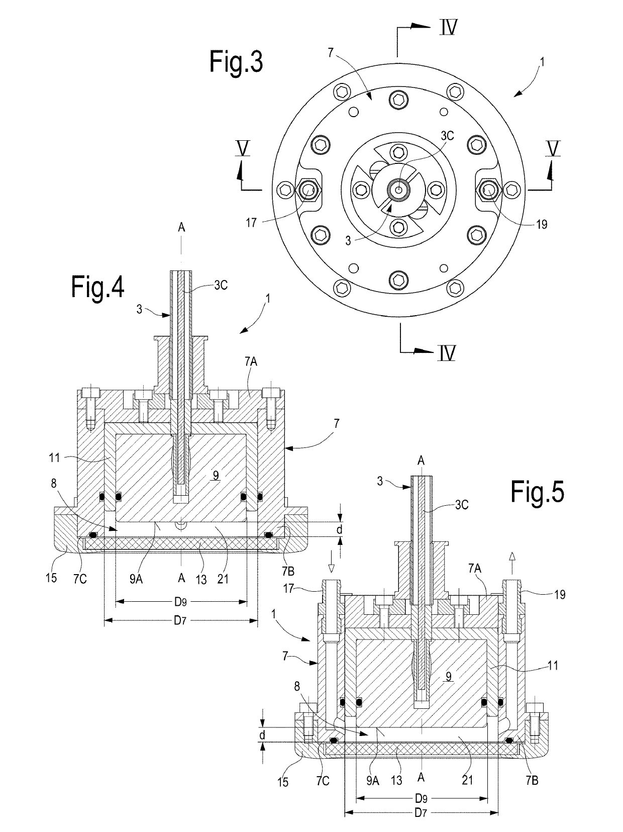
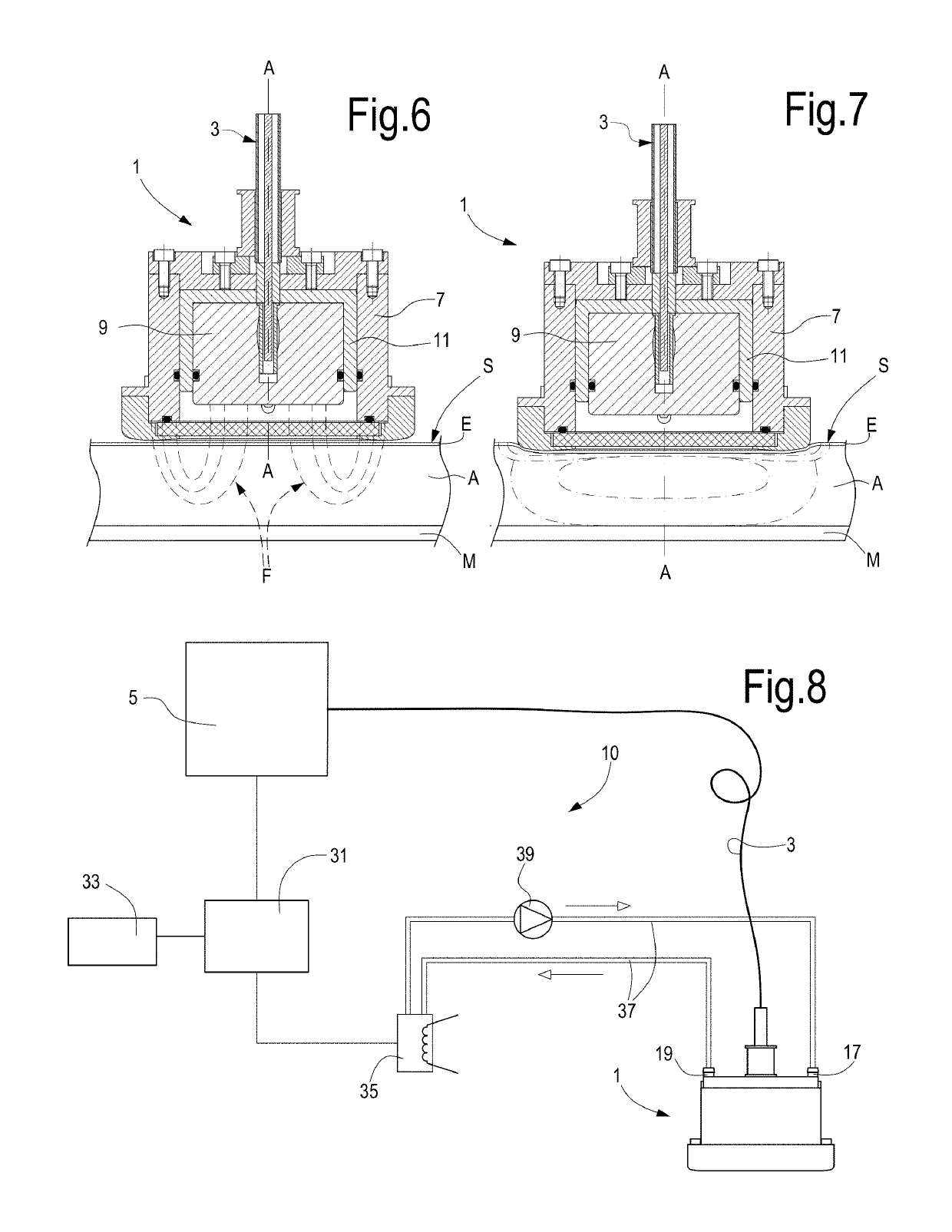
[0018]The window may be cooled, for instance by a coolant, which is dielectric in order to low electric losses and a good thermal conductor, and which flows along the inner surface of the closing plate, in order to avoid the risk of burns, as well as any feeling of localized overheating. In fact, the passage of radiofrequency energy through epidermis and derma causes therein heat production due to the transformation of electromagnetic energy into thermal energy and the consequent heating of the crossed tissues. The cooled window into contact with the epidermis removes heat and keeps the tissue temperature within acceptable values.

Problems solved by technology

Consequently, the current crosses sequentially, i.e. serially, the various layers, causing greater heat dissipation and therefore greater heating in the tissues having more resistivity.

Method used


Image

  • Delivery device with coaxial cable, apparatus comprising said device and method
  • Delivery device with coaxial cable, apparatus comprising said device and method
  • Delivery device with coaxial cable, apparatus comprising said device and method

Examples


Embodiment Construction

[0036]The following detailed description of the exemplary embodiments refers to the accompanying drawings. The same reference numbers in different drawings identify the same or similar elements. Additionally, the drawings are not necessarily drawn to scale. Also, the following detailed description does not limit the invention. Instead, the scope of the invention is defined by the appended claims.

[0037]Reference throughout the specification to “one embodiment” or “an embodiment” or “some embodiments” means that the particular feature, structure or characteristic described in connection with an embodiment is included in at least one embodiment of the subject matter disclosed. Thus, the appearance of the phrase “in one embodiment” or “in an embodiment” or “in some embodiments” in various places throughout the specification is not necessarily referring to the same embodiment(s). Further, the particular features, structures or characteristics may be combined in any suitable manner in one...


PUM


Abstract

The device includes an outer conductor (7) and an inner conductor (9) arranged approximately coaxial with each other. The outer conductor surrounds the inner conductor. The outer conductor (7) and the inner conductor (9) are arranged and configured to generate an electromagnetic field with lines of force extending from a front surface (9A) of the inner conductor (9) to a front surface (7C) of the outer conductor (7). The device further includes an energy delivery window (13) arranged in front of the outer conductor and the inner conductor.

Description

CROSS REFERENCE TO RELATED APPLICATIONS[0001]This application is a continuation-in-part of U.S. patent application Ser. No. 16 / 081,631 filed Aug. 31, 2018, and claims the benefit (35 U.S.C. § 120 and 365(c)) of International Application PCT / IB2017 / 051215 filed Mar. 2, 2017, which designated inter alia the United States and claims the benefit of priority of Italian Patent Application UA2016A001370, filed Mar. 4, 2016, the entire contents of each application are incorporated herein by reference.TECHNICAL FIELD[0002]The present invention relates to medical devices and apparatuses. More in particular, the invention relates to improvements to devices and apparatuses for removing adipose layers.BACKGROUND ART[0003]Nowadays, in the aesthetical treatment field the techniques for selective removal of adipose tissue have great significance. To this end, various methods have been developed over the years, some of which are based on invasive surgery. In less recent times, a treatment called lip...

Claims


Application Information

Patent Timeline
Patent Type & Authority Applications(United States)
IPC IPC(8): A61N2/02A61N2/00A61N1/40
CPCA61N2/02A61N2/004A61N1/403A61B2018/00464A61B18/1815A61B2018/00023A61B2018/183
Inventor MASOTTI, LEONARDOGALLI, MAUROSTOCCHI, RICCARDOCORSINI, PAOLOBINI, MARCOIGNESTI, AMLETORIMINESI, CRISTIANOBENI, SAMUELEPIERI, LAURACALLIGARO, ALBERTO
Owner EL EN SPA
Why Eureka
Try Eureka