
Determining the Ballistic Threshold Velocity for a Composite Structure Using Multiple Failure Models

a composite structure and ballistic threshold velocity technology, applied in the field of material failure analysis, can solve the problems of inability to accommodate complex materials, high cost, time-consuming, etc., and achieve the effect of reducing the cost of complex materials

Active Publication Date: 2019-08-22
THE BOEING CO
View PDF2 Cites 0 Cited by
  • Summary
  • Abstract
  • Description
  • Claims
  • Application Information

AI Technical Summary

Benefits of technology

The present patent relates to a device and technique for computing the ballistic threshold velocity of a composite structure, such as a laminated composite panel, using multiple material failure models (MFMs). The device generates a parametric model that weights each MFM based on its characteristics and physical properties, and uses a stress-based failure analysis, fracture-based failure analysis, or continuum damage failure analysis to determine the ballistic threshold velocity of the composite structure. The device can also obtain the weighting coefficients for each MFM from a previously generated parametric model or by fitting the model to empirical test data. The technical effect of the invention is to provide a more accurate and reliable method for computing the ballistic threshold velocity of composite structures.

Problems solved by technology

However, it is also expensive, time consuming, and can be very complex.
However, not only are conventional analytical methods are limited in their accuracy, but have historically proven to be incapable of accommodating complex materials, such as materials that are more complex than single isotropic materials.
Moreover, the results obtained using conventional analytical methods have historically been inaccurate when applied to complex materials having a complex shape.

Method used


Image

  • Determining the Ballistic Threshold Velocity for a Composite Structure Using Multiple Failure Models
  • Determining the Ballistic Threshold Velocity for a Composite Structure Using Multiple Failure Models
  • Determining the Ballistic Threshold Velocity for a Composite Structure Using Multiple Failure Models

Examples


Embodiment Construction

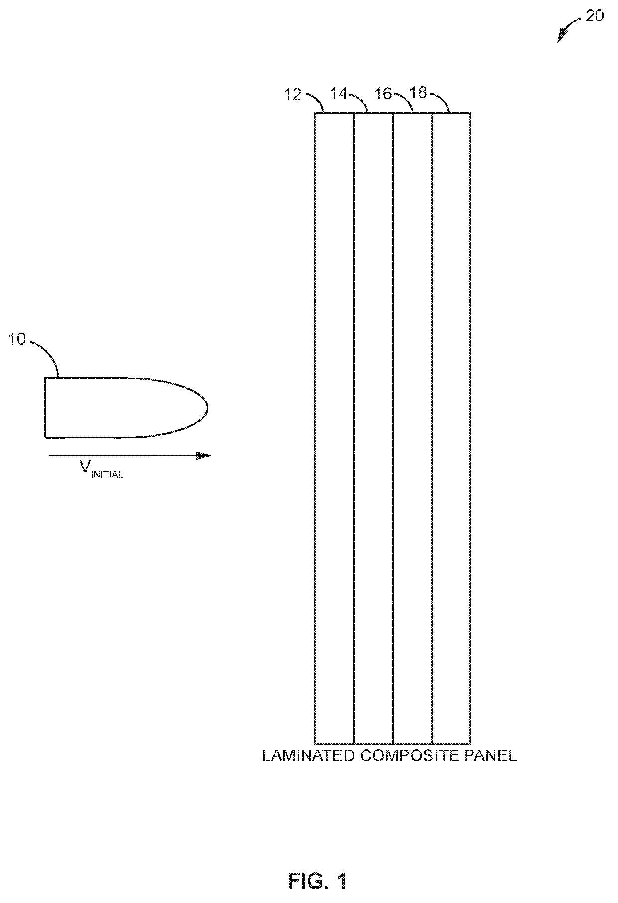
[0030]Aspects of the present disclosure relate to ballistic impact modeling for “composite structures” comprising multiple materials. Such composite structures include, but are not limited to, laminated composite panels comprising a plurality of different material layers.

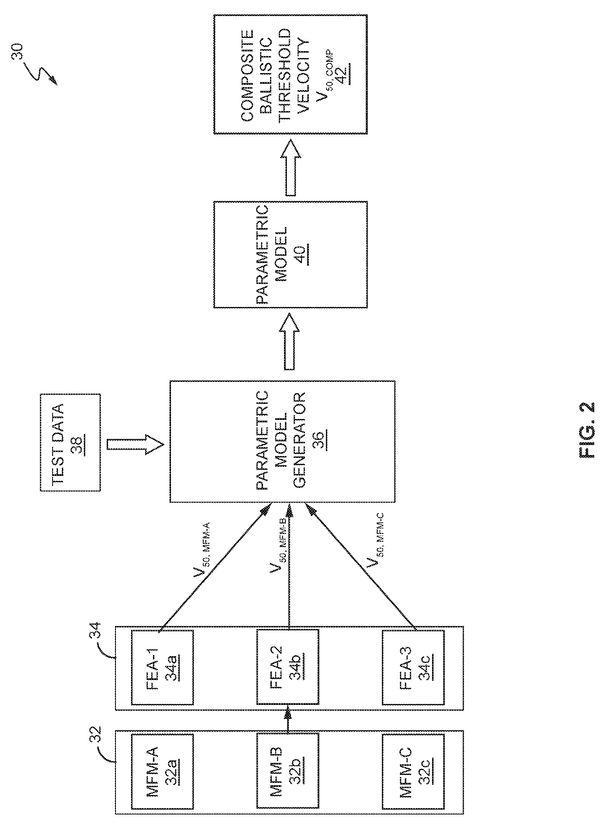
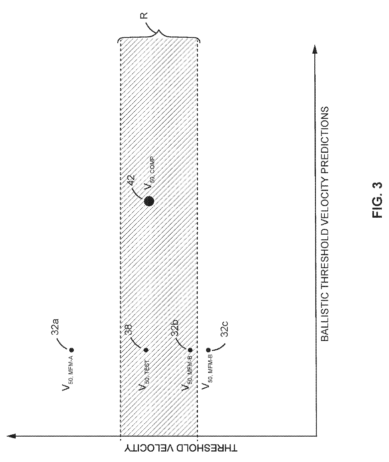
[0031]The ballistic threshold velocity V50 is defined as the velocity at which a projectile penetrates a given material 50% of the time. Usually, values for V50 are determined through extensive ballistic testing on the materials. However, in many cases, such experimentation is not possible, very costly, or simply not efficient to implement. Therefore, alternatively, V50 can be estimated using known finite element analysis (FEA) techniques. With these techniques, computers estimate the V50 of a given material to predict how certain ballistic-related stresses and loads will affect that particular material. Regardless of whether V50 is determined through experimentation or by utilizing a predictive FEA approach, though...


PUM


Abstract

A composite structure, such as a laminated composite panel, for example, comprises one or more layers or “plies” embedded in a matrix material or otherwise fixed together in an arrangement, commonly referred to as a “stack up.” Each material in the structure has a corresponding material failure model (MFM) defining the physical characteristics of that material. A ballistic threshold velocity computing device obtains the MFMs for each material in the composite structure, generates a predicted ballistic velocity threshold velocity for each MFM, and then generates a parametric model to compute a composite ballistic velocity threshold velocity for the composite structure.

Description

STATEMENT OF POTENTIAL GOVERNMENT RIGHTS[0001]The invention described herein was made in the performance of work under NASA Contract No. NNL09AA00A and is subject to the provisions of Section 305 of the National Aeronautics and Space Act of 1958 (72 Stat. 435: 42 U.S.C. 2457).TECHNICAL FIELD[0002]The present disclosure relates generally to the field of material failure analysis, and more particularly, to predicting the ballistic threshold velocity for a composite structure using a plurality of material failure models (MFMs).BACKGROUND[0003]The ballistic threshold velocity V50 is defined as the velocity at which a projectile penetrates a material 50% of the time. Knowing V50 is beneficial when designing a structure that can adequately withstand a ballistic impact from a projectile travelling at a given velocity. Historically, values for V50 are determined for a given material using one of two methods. Particularly, the V50 of a given material can be determined through extensive balli...

Claims


Application Information

Patent Timeline
IPC IPC(8): G06F17/50G06F7/544
CPCG06F17/5009G06F7/544F41H5/04F41H5/00G06F30/17G06F2113/26G06F30/20G06F2119/02
Inventor HUNZIKER, KENNETH JOSEPHIQBAL, JAFFAR SHERPANG, JENNA KRISTINRASSAIAN, MOSTAFA
Owner THE BOEING CO
Learn More