
Method for Transmitting Carrier, Base Station, User Equipment, and System

a transmission method and carrier technology, applied in the field of wireless communications technologies, can solve the problems of no actual application scenario of carrier overlapping in the prior, mutual interference between carriers, and waste of spectrum resources, so as to avoid causing mutual interference between carriers and improve resource utilization rate

Active Publication Date: 2019-08-22
HUAWEI TECH CO LTD
View PDF0 Cites 8 Cited by
  • Summary
  • Abstract
  • Description
  • Claims
  • Application Information

AI Technical Summary

Benefits of technology

The technical solution in this patent improves resource utilization in a communication system by sharing a resource area between two carriers. This can be done by making the carriers completely overlap, partially overlap, or excessively overlap in the same resource area. The base station notifies the UE of the empty resource element indication information, so the UE can identify the position of the resource element occupied by the first carrier and receive signals without using those positions, thereby avoiding interference with the first carrier. This compatibility between different systems can be effectively implemented and the resource utilization rate is improved. Overall, the technical solution enhances efficiency and reliability of the communication system.

Problems solved by technology

However, when the carrier bandwidth is fixed, spectrum resources are wasted when the spectrum is irregular.
However, there is no actual application scenario of carrier overlapping in the prior art.
However, at an overlapping part of two carriers, if the two carriers simultaneously transmit a signal by using a same time-frequency resource, mutual interference between the carriers is caused.
Consequently, the two carriers cannot normally work.

Method used


Image

  • Method for Transmitting Carrier, Base Station, User Equipment, and System
  • Method for Transmitting Carrier, Base Station, User Equipment, and System
  • Method for Transmitting Carrier, Base Station, User Equipment, and System

Examples


Embodiment Construction

[0049]The following clearly describes technical solutions in embodiments of the present invention with reference to the accompanying drawings in the embodiments of the present invention.

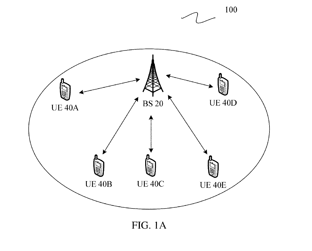
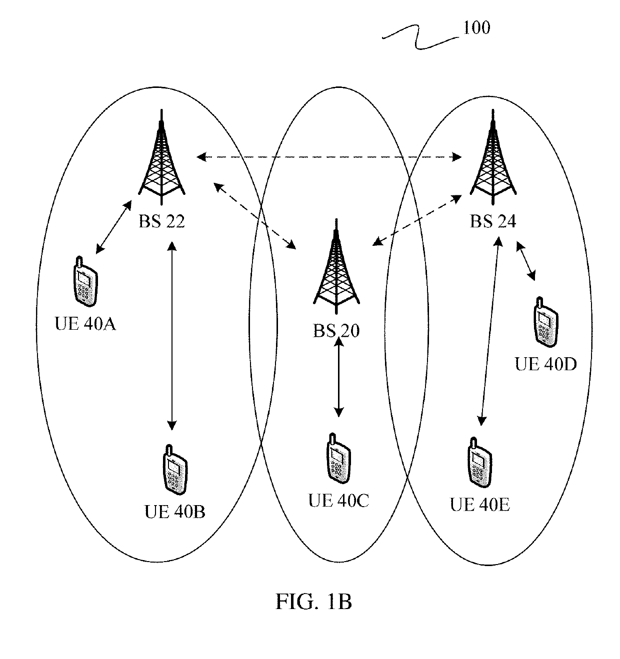
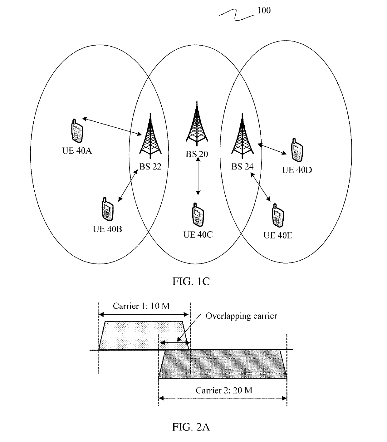
[0050]To resolve a problem in the prior art that in an existing communications system, mutual interference exists between carriers during carrier overlapping, and consequently the carriers cannot normally work, the embodiments of the present invention provide a solution based on a communications system shown in FIG. 1A, FIG. 1B, or FIG. 1C, to cancel interference between carriers while improving a resource utilization rate of the communications system.

[0051]As shown in FIG. 1A, FIG. 1B, and FIG. 1C, the embodiments of the present invention provide a communications system 100. The communications system 100 includes at least one base station (BS) and a plurality of UEs. For example, in FIG. 1A, FIG. 1B, and FIG. 1C, the plurality of UEs may be separately identified as UE 40A to UE 40E.

[0052]In the solu...


PUM


Abstract

The present invention relates to the field of wireless communications technologies, and provides a method for transmitting a carrier, a base station, user equipment, and a system. The method discloses: sending, by a base station, a second carrier, where the second carrier at least partially shares a same resource area with a first carrier, the resource area includes a plurality of resource elements, and the first carrier and the second carrier occupy different resource elements; and sending, by the base station, blank resource element indication information to user equipment that receives the second carrier, where the blank resource element indication information is used to indicate a position of a resource element occupied by the first carrier in the shared resource area. According to the solutions provided in the embodiments, a resource utilization rate of a communications system is improved, and interference between carriers is avoided.

Description

CROSS-REFERENCE TO RELATED APPLICATIONS[0001]This application is a continuation of International Application No. PCT / CN2017 / 104548, filed on Sep. 29, 2017, which claims priority to Chinese Patent Application No. 201610966093.2, filed on Nov. 4, 2016. The disclosures of the aforementioned applications are hereby incorporated by reference in their entireties.TECHNICAL FIELD[0002]The present invention relates to the field of wireless communications technologies, and in particular, to a method for transmitting a carrier, a base station, user equipment, and a system.BACKGROUND[0003]In a wireless communications system, each carrier is usually deployed in a frequency division multiplexing (FDM) manner, and a guard interval is reserved between two carriers. For example, a carrier 1 occupies a fixed bandwidth of 10 MHz, a carrier 2 occupies a fixed bandwidth of 20 MHz, and a guard interval bandwidth is reserved between the carrier 1 and the carrier 2.[0004]A conventional carrier bandwidth is...

Claims


Application Information

Patent Timeline
Patent Type & Authority Applications(United States)
IPC IPC(8): H04W72/04H04L5/00H04W72/08H04W72/54
CPCH04W72/0453H04L5/0048H04W72/082H04W72/541H04W72/23H04L5/001H04L5/0007H04L5/0044H04W72/12H04W72/04H04W72/54
Inventor ZHOU, GUOHUATANG, ZHENFEIZHAO, YUEYINGTANG, HAOZHANG, PENGWEI, DONGDONG
Owner HUAWEI TECH CO LTD
Learn More