Surgical stapler having a powered handle

a surgical stapler and powered technology, applied in the field of surgical occlusion instruments, can solve the problems of increased manufacturing burden of surgical staplers, confusion for users, and potential sources of device failur

Active Publication Date: 2019-08-29
APPL MEDICAL RESOURCES CORP
View PDF0 Cites 604 Cited by
  • Summary
  • Abstract
  • Description
  • Claims
  • Application Information

AI Technical Summary

Benefits of technology

[0010]In certain embodiments a handle assembly for a surgical stapler is provided. The handle assembly comprises a handle body, a power system, an actuation shaft, a position sensor, and a control system. Thea handle body comprises a stationary handle and a trigger movably coupled to the handle body. The power system is within the handle body. The power system comprises a motor and a power source positionable within the handle body. The actuation shaft is operatively coupled to the power system. The actuation shaft is longitudinally slidable within the handle body. The position sensor is configured to determine the longitudinal position of the actuation shaft. The control system is electrically coupled to the power system, the trigger, and the position sensor. The control system is configured to define a motor drive logic profile to define at least one operational parameter for the motor at a position of the actuation shaft corresponding to a grasper zone, a lockout zone, and a firing zone.
[0011]In certain embodiments a handle assembly for a surgical stapler having a removably coupled instrument shaft havi...

Problems solved by technology

With these complex mechanisms, surgical staplers can have increased manufacturin...

Method used


Image

  • Surgical stapler having a powered handle
  • Surgical stapler having a powered handle
  • Surgical stapler having a powered handle

Examples


Embodiment Construction

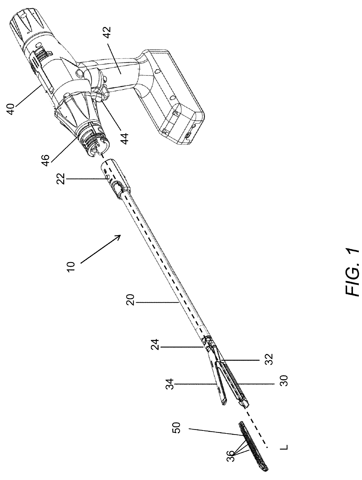
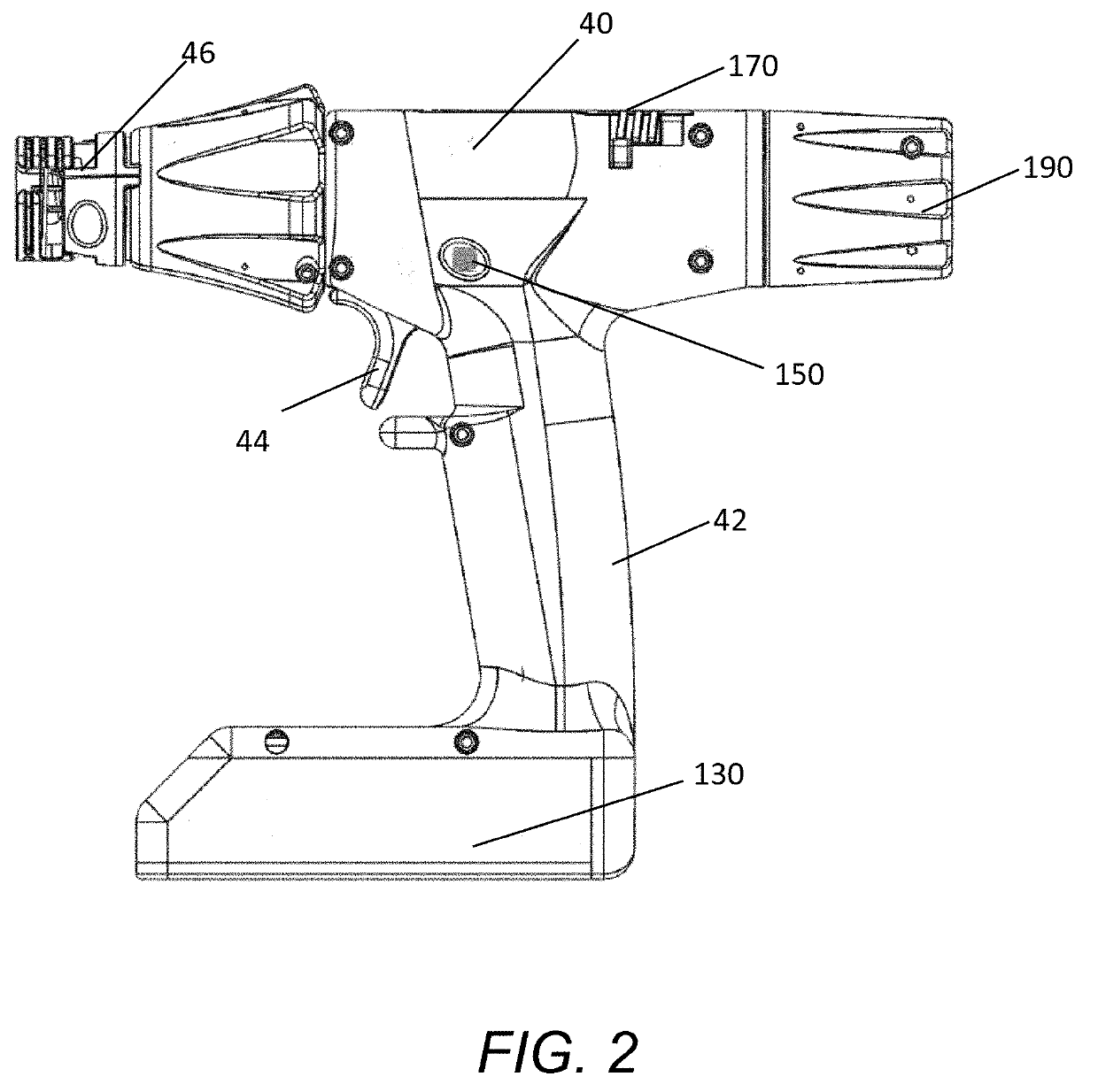
[0082]With reference to FIGS. 1-2, an embodiment of surgical stapling system is illustrated. The illustrated embodiment of surgical stapler 10 comprises an elongate shaft 20, a jaw assembly 30, and a handle assembly 40. FIG. 1 illustrates the surgical stapler 10 with the jaw assembly 30 in an open configuration with an embodiment of powered handle having powered staple firing and manual jaw assembly articulation. FIG. 2 illustrates the powered handle 40 of the surgical stapler system 10 with the elongate shaft removed. The powered handle 40 of FIG. 2 has powered staple firing and manual jaw assembly articulation. In the illustrated embodiments, the shaft 20 and jaw assembly 30 can be freely rotated about a longitudinal axis defined by the shaft 20 by rotation of a rotation knob on the handle 40. In other embodiments, the stapling system can be configured to allow rotation of the jaw assembly about the longitudinal axis within a predefined range or a rotationally fixed jaw assembly.

[...


PUM


Abstract

A powered handle for a surgical stapler can have a drive system including an electric motor. The powered handle can include a manual articulation mechanism to articulate a jaw assembly coupled to a reload shaft connected to the handle. The manual articulation mechanism can include a ball screw mechanism that translates an articulation member responsive to rotation of an articulation knob when an instrument shaft is engaged with the handle. The articulation mechanism includes a release function that allows the jaw assembly to return to a longitudinally centered orientation. The powered handle includes a battery pack serving as a power supply for the drive system. A control system can control actuation of the motor based on user inputs and operating parameters of the stapler and can provide certain motor drive profiles for predetermined positions of the stapler. The powered handle can include a manual return mechanism.

Description

CROSS REFERENCE TO RELATED APPLICATIONS[0001]This application claims the benefit of U.S. Provisional Patent Application Ser. No. 62 / 636,070, filed Feb. 27, 2018, entitled “Surgical Stapler Having a Powered Handle,” and U.S. Provisional Patent Application Ser. No. 62 / 734,154, filed Sep. 20, 2018, entitled “Surgical Stapler Having a Powered Handle.” Each of which is hereby incorporated herein by reference in its entirety.BACKGROUND OF THE INVENTIONField of the Invention[0002]The present application relates generally to surgical occlusion instruments and, more particularly, to powered surgical staplers.Description of the Related Art[0003]Surgical staplers are used to approximate or clamp tissue and to staple the clamped tissue together. As such, surgical staplers have mechanisms to clamp tissue and to drive staples through the tissue. As a result, this has produced, for example, multiple triggers and handles in conjunction with complex mechanisms to provide proper stapling of the clamp...

Claims


Application Information

Patent Timeline
IPC IPC(8): A61B17/072
CPCA61B17/07207A61B2017/00115A61B2017/0042A61B2017/0019A61B2017/00398A61B2017/00734A61B2017/2946A61B2017/0023A61B2017/2925A61B2017/0046A61B2090/0811A61B2017/07285A61B2017/07271A61B2017/00017A61B2017/00407A61B2017/2923A61B2017/2927A61B2018/00297A61B2090/0807A61B2090/0814A61B2090/064
Inventor NELSON, ERIK D.NASH, JONATHAN R.HOPKINS, TIMOTHY M.HUDSON, KEVINPHAM, ANDYGYUGYI, ZACHARY W.SPALDING, JOSHUA A.HALVORSEN, CHRISTIAN A.
Owner APPL MEDICAL RESOURCES CORP
Why Eureka
Try Eureka