Conductor module for terminal

Active Publication Date: 2019-09-05
YAZAKI CORP
View PDF0 Cites 9 Cited by
  • Summary
  • Abstract
  • Description
  • Claims
  • Application Information

AI Technical Summary

Benefits of technology

[0006]In view of the foregoing, an object of the present invention is to provide a conductor module for termina

Problems solved by technology

When an external force works on the connecting unit, the connecting unit may be damaged and connection reliability of a conductor module for te

Method used


Image

  • Conductor module for terminal
  • Conductor module for terminal
  • Conductor module for terminal

Examples


first embodiment

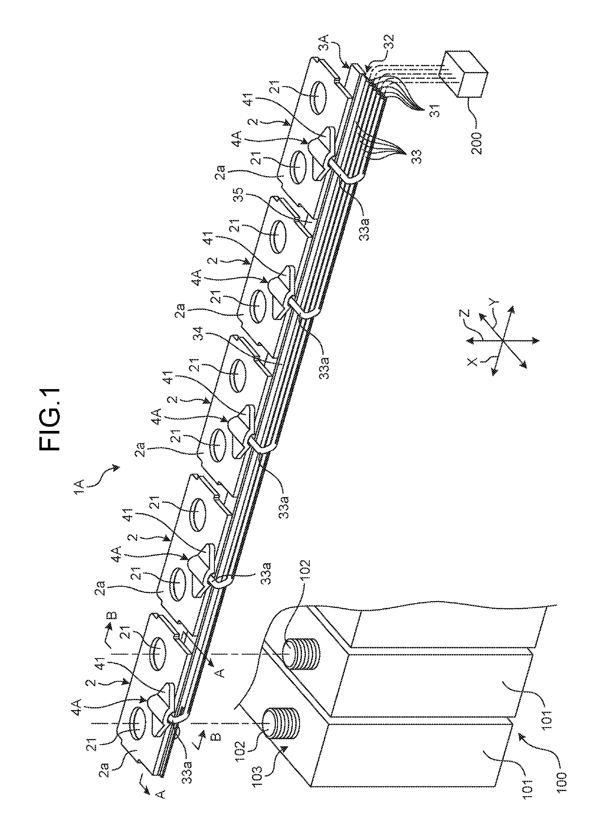
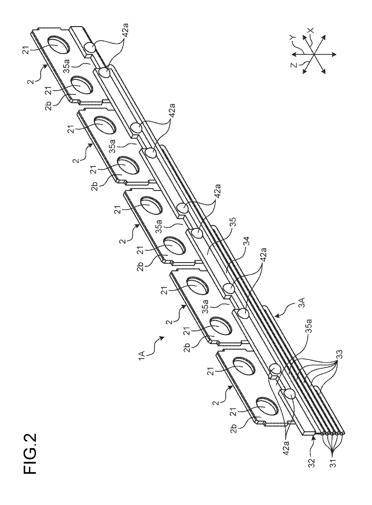
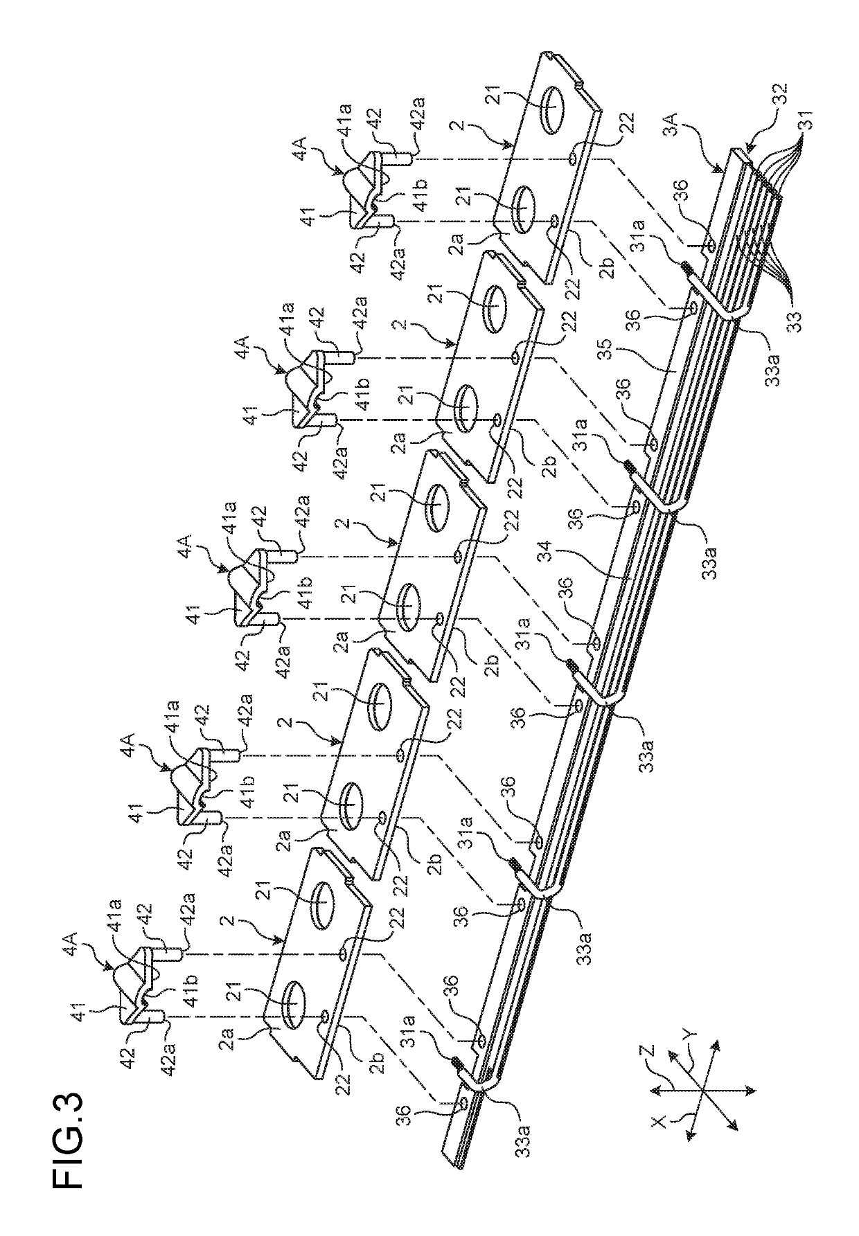
[0025]A conductor module for terminal in accordance with a first embodiment will now be described. FIG. 1 is a perspective view illustrating the conductor module for terminal in accordance with the first embodiment. FIG. 2 is a perspective view illustrating the conductor module for terminal in accordance with the first embodiment. FIG. 3 is an exploded perspective view illustrating the conductor module for terminal in accordance with the first embodiment. FIG. 4 is a sectional view illustrating a main part of the conductor module for terminal in accordance with the first embodiment. FIG. 5 is a sectional view illustrating a main part of the conductor module for terminal in accordance with the first embodiment. FIG. 4 is a sectional view along line A-A of FIG. 1, and FIG. 5 is a sectional view along line B-B of FIG. 1. X direction in each of the drawings (including FIGS. 6 to 9) indicates an arrangement direction of electrode terminals and bus bars according to the embodiments. Y dir...

second embodiment

[0045]A conductor module for terminal 1D in accordance with a second embodiment will now be described. FIG. 8 is a perspective view illustrating a conductor module for terminal in accordance with the second embodiment. FIG. 9 is a sectional view illustrating a main part of the conductor module for terminal in accordance with the second embodiment. FIG. 9 is a sectional view along line C-C of FIG. 8. The conductor module for terminal 1D according to the second embodiment is different from the conductor module for terminal 1A according to the first embodiment in that each of the bus bars 2 and a state detector 3D are connected to each other through fixing members 4B. Like numerals are assigned to like components as those of the conductor module for terminal 1A according to the first embodiment, and explanation thereof is omitted or simplified.

[0046]The conductor module for terminal 1D includes the plurality of bus bars 2, the state detector 3D, and the plurality of fixing members 4B a...


PUM


Abstract

A conductor module for terminal includes a bus bar, a state detector including a detection conductor, and a fixing member fixing the state detector to the bus bar. The bus bar includes a connection surface to which the detection conductor is electrically connected, and two fixing holes formed with the placed state detector interposed therebetween. The fixing member includes a main body that the state detector is made contact with, and plastically deformable fixing legs. Each of the fixing legs is inserted in the fixing hole from the connection surface side and projects from the fixed surface. In a fixed state, when the fixing leg is seen from an axis direction of the fixing hole, a tip of the fixing leg is disposed on the outside in a radial direction than the fixing holes.

Description

CROSS-REFERENCE TO RELATED APPLICATION(S)[0001]This application is a continuation application of International Application PCT / JP2017 / 045380, filed on Dec. 18, 2017, which claims priority to Japanese Patent Application No. 2016-245831, filed on Dec. 19, 2016 and designating the U.S., the entire contents of which are incorporated herein by reference.BACKGROUND OF THE INVENTION1. Field of the Invention[0002]The present invention relates to a conductor module for terminal.2. Description of the Related Art[0003]There has been a conductor module for terminal used for a battery module that includes a plurality of battery cells. The conductor module for terminal includes, for example, a bus bar that is electrically connected to either of two electrode terminals in a battery cell and is electrically connected to electrode terminals in adjacent battery cells, and a voltage detector that includes a detection conductor for detecting a voltage of a battery cell (see Japanese Patent No. 5223607)...

Claims


Application Information

Patent Timeline
IPC IPC(8): H01M2/20H01R11/28H01R4/48H01R4/06H01M10/48H01M2/34H01M50/209H01M50/262H01M50/50H01M50/505H01M50/51H01M50/569
CPCH01M2/206H01R11/288H01M2/34H01R4/06H01M10/48H01R4/48H01M10/482Y02E60/10H01M50/50H01M50/209H01M50/51H01M50/505H01M50/569H01M50/262
Inventor SATO, KATSUNORIGOTO, TAKUTOYANAGIHARA, SHINICHIICHIKAWA, YOSHIAKISHOJI, TAKAO
Owner YAZAKI CORP
Why Eureka
Try Eureka