Motor cable device and resin component employed thereto

a technology of resin components and motor cables, which is applied in the direction of cable arrangements between relatively moving parts, coupling device connections, instruments, etc., can solve the problems of lowering etc., to prevent the lowering of the connection reliability of prevent damage to the inverter-side connection member, and good connection condition

Active Publication Date: 2012-05-08
YAZAKI CORP
View PDF8 Cites 7 Cited by
  • Summary
  • Abstract
  • Description
  • Claims
  • Application Information

AI Technical Summary

Benefits of technology

[0010]However, when the swinging motion is generated at the cable body, a force induced by this swinging motion may have an influence especially on the inverter-side connecting member. Thus, according to the above-described idea, there is still a risk of damaging the inverter-side connecting member and lowering a connecting reliability of the inverter-side connecting member.
[0011]In view of the above-described problems, an object of the present invention is to provide a motor cable device which can prevent damage on the inverter-side connecting member of the motor cable device and which can prevent lowering in a connecting reliability of the inverter-side connecting member. Another object of the present invention is to provide a resin component used in the above-described motor cable device.
[0013]According to the motor cable device as described above, the vibration of the motor and such is transmitted to the cable body, generating the swinging motion to the cable body. This swinging motion of the cable body at the swinging-motion absorbing portion can be absorbed by the swinging-motion absorbing portion formed at the resin component fixed to the inverter, preventing effect by a force of the swinging motion to the inverter-side connecting member connected to the inverter. As a result, damage on the inverter-side connecting member and lowering in a connecting reliability of the inverter-side connecting member can be prevented.
[0015]According to the invention described above, by using the recess, the shape of the cable body from the recess towards the motor can be easily formed into a non-planer shape. For example, if the cable body has three cables, one of the three cables in middle is placed at the recess and pulled out from the resin portion. Then, the rest of the cables on both sides of the middle cable are pulled out from the resin portion so as to gather inwardly. As a result, the cable body with three cables can be easily formed into a non-planer shape with a triangular cross section. Furthermore, providing the recess is also useful in order to assemble (band together) the plurality of cables in a predetermined position.
[0016]In a case of bending the cable body when wiring, the respective three cables are required to be different in lengths, giving a consideration regarding to looseness (or yield). If, for example, the cable body has the triangular cross section as described above, the cable body cannot be bent to be wired unless the cables are accurately aligned. However, by using the recess of the invention, the three cables can be banded (bundled together) in a predetermined position, thus the cable body can be bent and wired unimpededly. Furthermore, since the recess is formed at a part of the free end of the swinging-motion absorbing portion, the recess will not impair the function of the swinging-motion absorbing portion.
[0020]According to the invention described above, the swinging motion generated at the cable body can be absorbed by the swinging-motion absorbing portion. Thus, the inverter-side connecting member connected to the inverter will not be affected by the swinging motion, keeping a good connecting condition. Consequently, the resin component which can prevent damage on the inverter-side connecting member and which can prevent lowering in a connecting reliability of the inverter-side connecting member can be provided.

Problems solved by technology

Thus, according to the above-described idea, there is still a risk of damaging the inverter-side connecting member and lowering a connecting reliability of the inverter-side connecting member.

Method used


Image

  • Motor cable device and resin component employed thereto
  • Motor cable device and resin component employed thereto
  • Motor cable device and resin component employed thereto

Examples


Embodiment Construction

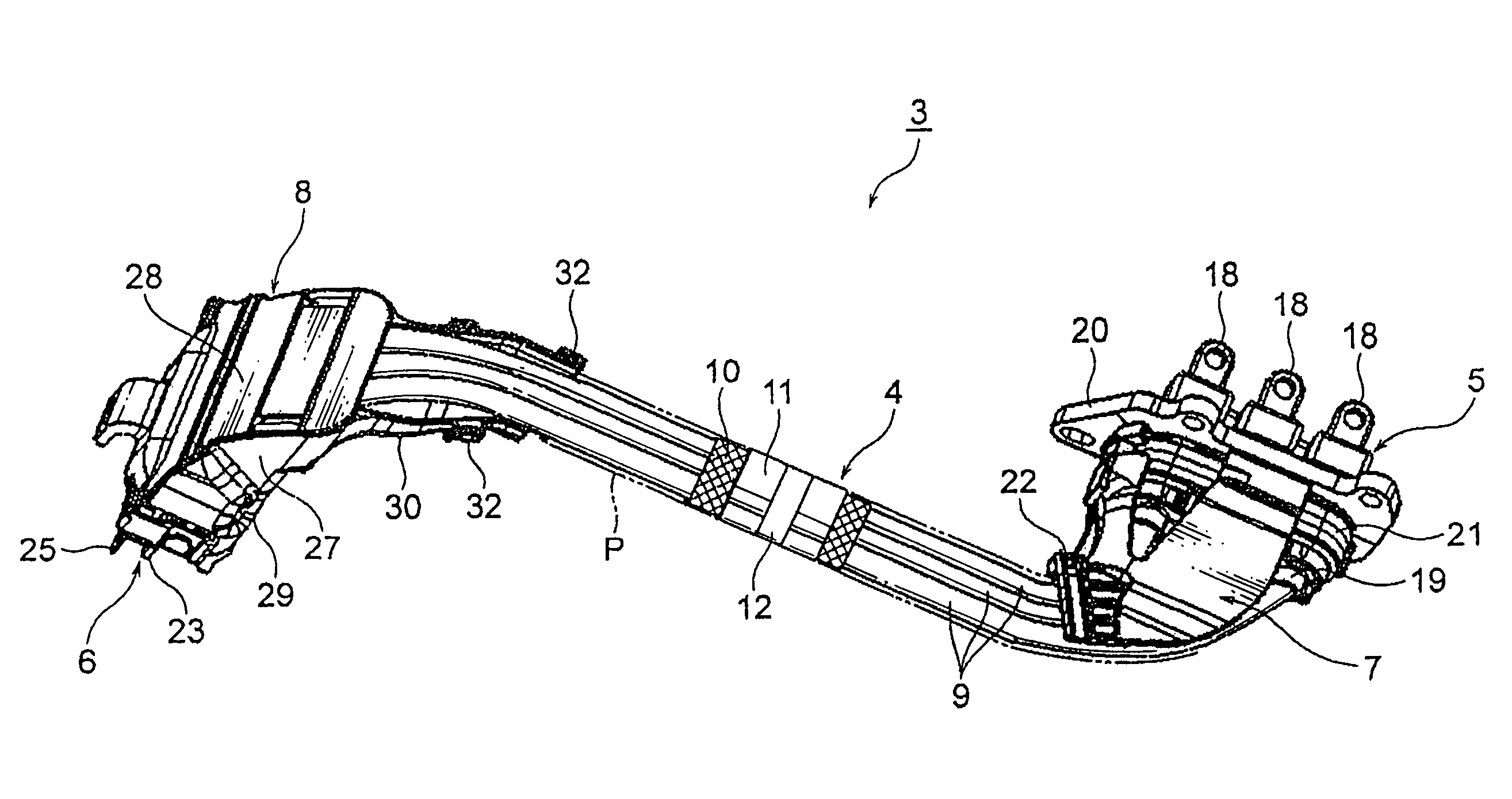
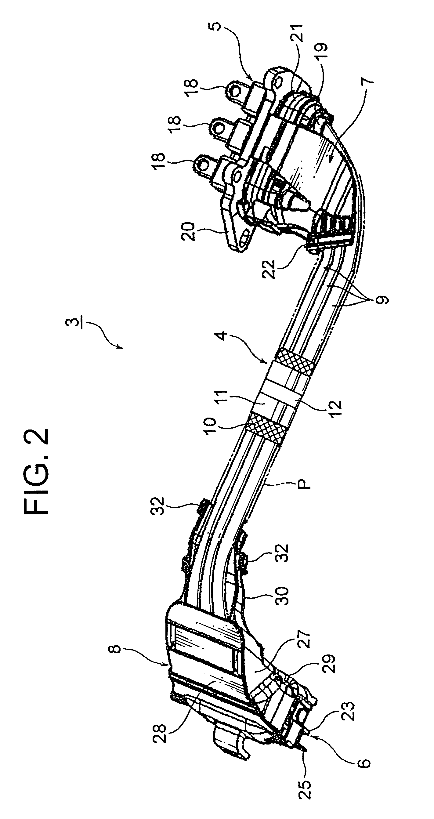
[0029]A motor cable device, electrically connecting a motor and an inverter, includes a resin component. This resin component has a fixed end which is fixed to the inverter directly or indirectly, and which supports an inverter-side connecting member of the motor cable device. The resin component also has a swinging motion absorbing portion continuous to the fixed end which supports a cable body adjacent the inverter-side connecting member and absorbs swinging motion of the cable body. The motor cable device includes the above-described resin component and the cable body at which the swinging motion is generated.

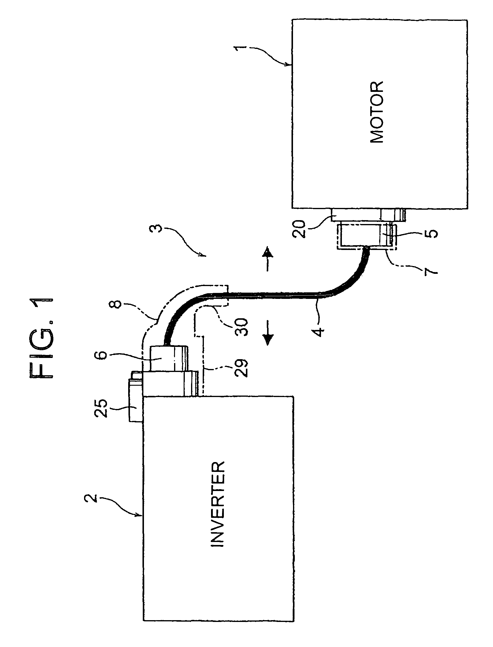
[0030]A first exemplary embodiment is explained below with reference to FIGS. 1 through 6. FIG. 1 is a schematic illustration of the motor cable device according to the present invention in use, FIG. 2 is a perspective view of the inventive motor cable device, FIG. 3 is a perspective view of the inverter-side connecting member and a protector of the motor cable device, FIG. ...


PUM


Abstract

The motor cable device which can prevent damage on an inverter-side connecting member of the motor cable device and lowering in a connecting reliability of the inverter-side connecting member is provided. Also, a resin component used in the above-described motor cable device is provided. The motor cable device electrically connects a motor and an inverter and includes an inverter-side protector and a motor-side protector. The inverter-side protector includes a fixed end which is directly or indirectly fixed to the inverter and which supports the inverter-side connecting member. A swinging motion absorbing portion is formed continuously to the fixed end, the swinging motion absorbing portion being arranged to support a cable body at the inverter-side connecting member and absorb the swinging motion generated at the cable body of the motor cable device, is further included.

Description

CROSS-REFERENCE TO RELATED APPLICATIONS[0001]This application claims priority to Japanese Patent Application Number 2009-82042 filed on Mar. 30, 2009, the contents of which are fully incorporated herein by reference.BACKGROUND[0002]1. Field of the Invention[0003]The present invention relates to a motor cable device electrically connecting a motor and an inverter, and a resin component used in the motor cable device.[0004]2. Description of Related Art[0005]An electric motor vehicle and a hybrid motor vehicle have a motor for a power source, an inverter generating three-phase AC necessary to drive the motor, and a motor cable device connecting the motor and the inverter.[0006]Japan Patent Application Publication Number 2008-253017 discloses a motor cable device having a cable body including a plurality of cables, a motor-side connecting member provided at one end of the cable body to which the motor is connected, and an inverter-side connecting member provided at the other end of the ...

Claims


Application Information

Patent Timeline
Patent Type & Authority Patents(United States)
IPC IPC(8): H01R13/56
CPCH02G3/0437H02G11/00H02K5/225H02G3/0608H02K11/0073H02K11/33
Inventor ADACHI, HIDEOMIKUBOSHIMA, HIDEHIKO
Owner YAZAKI CORP
Why Eureka
Try Eureka