Suspension board with circuit

a suspension board and circuit technology, applied in the direction of metallic pattern materials, record information storage, instruments, etc., can solve the problems of reducing the reliability of connecting the terminals, insulating the layer easily and absorbing a lot of energy, and causing more burns, etc., to achieve excellent reliability

Inactive Publication Date: 2012-08-02
NITTO DENKO CORP
View PDF4 Cites 6 Cited by
  • Summary
  • Abstract
  • Description
  • Claims
  • Application Information

AI Technical Summary

Benefits of technology

[0009]However, in a terminal portion, when a metal is heated and melted with a high energy density including a case where laser light is applied to the metal such as the solder ball, a disadvantage may occur, such as that an insulating layer is burned around the terminal portion, so that the connecting reliability between the terminals may be reduced.
[0033]In the suspension board with circuit, the melted metal enters into the cut-out portion in the terminal portion, so that the melted metal is fixed to the terminal portion further reliably and therefore, the terminal can be connected with the excellent reliability.

Problems solved by technology

However, in a terminal portion, when a metal is heated and melted with a high energy density including a case where laser light is applied to the metal such as the solder ball, a disadvantage may occur, such as that an insulating layer is burned around the terminal portion, so that the connecting reliability between the terminals may be reduced.
Above all, when the insulating layer is formed of a dark colored resin such as an aromatic polyimide, there is a disadvantage that the insulating layer easily absorbs a lot of energy, so that a burn is more likely to occur because of low permeability of the laser light in the insulating layer.

Method used


Image

  • Suspension board with circuit
  • Suspension board with circuit
  • Suspension board with circuit

Examples


Embodiment Construction

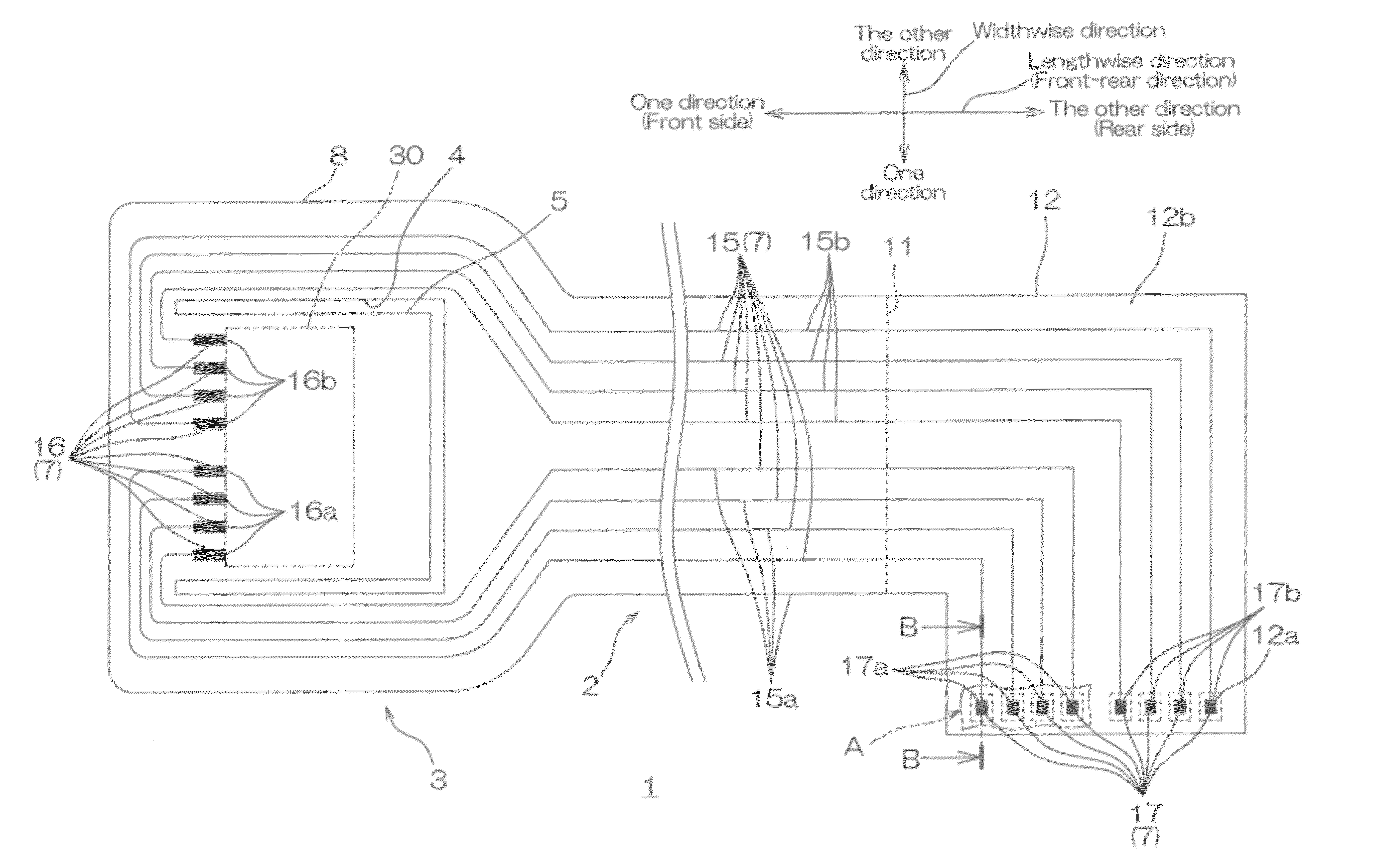
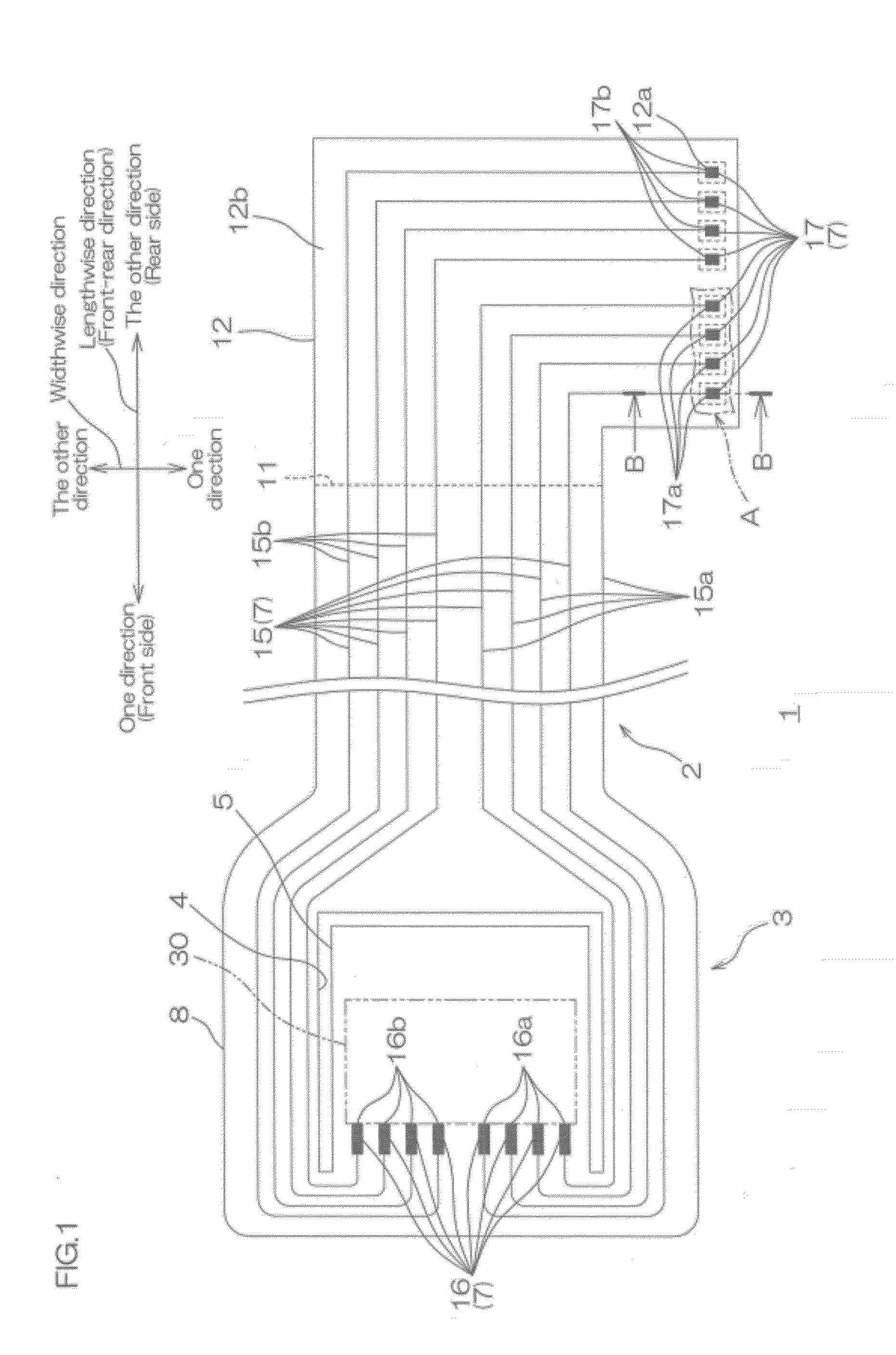
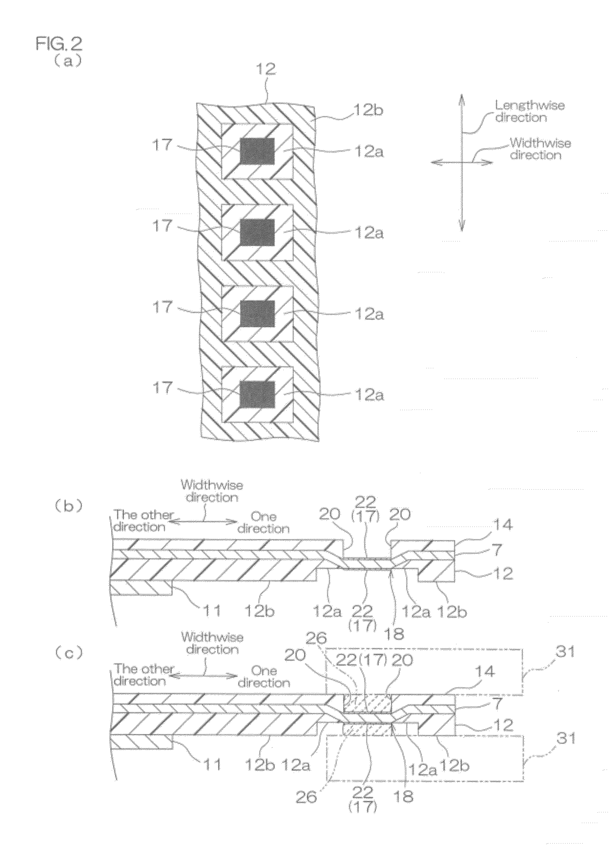
[0070]FIG. 1 shows a plan view of one embodiment of a suspension board with circuit of the present invention. FIG. 2 shows configuration views of essential parts of the suspension board with circuit shown in FIG. 1: FIG. 2 (a) illustrating an enlarged bottom view of a region A of an external-side terminal portion of the suspension board with circuit shown in FIG. 1, FIG. 2 (b) illustrating an enlarged sectional view, taken along the line B-B of the suspension board with circuit shown in FIG. 1, and FIG. 2 (c) illustrating an enlarged sectional view, taken along the line B-B, showing a connecting state of the suspension board with circuit shown in FIG. 1 with an external circuit board.

[0071]In FIG. 1, an insulating cover layer 14 to be described later is omitted so as to clearly show the relative arrangement of a conductive pattern 7 to be described later.

[0072]In FIGS. 1 and 2, a suspension board with circuit 1 is mounted with a magnetic head (not shown) in a hard disk drive and sup...


PUM


Abstract

A suspension board with circuit includes an insulating base layer and a conductive pattern that is laminated on a top surface of the insulating base layer. The conductive pattern includes a wire and a terminal portion that is connected to the wire for being joined by a melted metal. The insulating base layer, in a projected surface when projected in a laminating direction, includes an adjacent region that is adjacent to the terminal portion and a separated region that is separated from the terminal portion so as to sandwich the adjacent region with the terminal portion. The adjacent region is formed to be thinner than the separated region.

Description

CROSS-REFERENCE TO RELATED APPLICATION[0001]The present application claims the benefit of U.S. Provisional Application No. 61 / 457,257 filed on Feb. 11, 2011, and claims priority from Japanese Patent Application No. 2011-19984 filed on Feb. 1, 2011, the contents of which are hereby incorporated by reference into this application.BACKGROUND OF THE INVENTION[0002]1. Field of the Invention[0003]The present invention relates to a suspension board with circuit, to be specific, to a suspension board with circuit that is used in a hard disk drive.[0004]2. Description of Related Art[0005]Conventionally, it has been widely known that a suspension board with circuit is used in a hard disk drive. The suspension board with circuit includes a suspension and a conductive pattern that is formed thereon having a head-side terminal portion so as to be connected to a magnetic head and an external-side terminal portion so as to be connected to an external board. The suspension board with circuit is mou...

Claims


Application Information

Patent Timeline
Patent Type & Authority Applications(United States)
IPC IPC(8): H05K1/02H05K1/00
CPCG11B5/4846G11B5/486G11B5/4853
Inventor ISHIGAKI, SAORIKANAGAWA, HITOKIFUJIMURA, YOSHITO
Owner NITTO DENKO CORP
Why Eureka
Try Eureka