Radio-frequency switch and communication device

Active Publication Date: 2019-09-05
MURATA MFG CO LTD
View PDF0 Cites 9 Cited by
  • Summary
  • Abstract
  • Description
  • Claims
  • Application Information

AI Technical Summary

Benefits of technology

The patent improves RF switches and communication devices by making them better at supporting carrier aggregation (CA) and increasing isolation. This means that the devices can handle more data and have better protection against interference.

Problems solved by technology

However, the above-described switch circuit of the related art does not support CA and a way of increasing isolation in a switch circuit that supports CA is not disclosed.

Method used


Image

  • Radio-frequency switch and communication device
  • Radio-frequency switch and communication device
  • Radio-frequency switch and communication device

Examples


embodiment 1

Preferred Embodiment 1

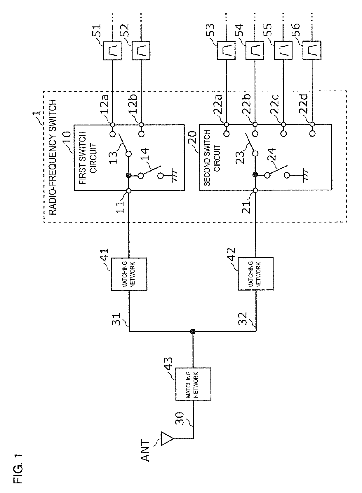
[0046]FIG. 1 is a configuration diagram of a radio-frequency switch 1 according to a preferred embodiment 1 of the present invention and circuits peripheral thereto. In FIG. 1, in addition to the radio-frequency switch 1, an antenna ANT, matching networks 41 to 43, and filters 51 to 56 are illustrated.

[0047]The antenna ANT transmits and receives radio-frequency signals and supports multiple bands in accordance with a communication standard, such as long term evolution (LTE), for example.

[0048]The radio-frequency switch 1 supports carrier aggregation (CA) in which at least two different frequency bands are simultaneously used, and is provided in the front end of a communication device, such as a cellular phone, for example. In the present preferred embodiment, the radio-frequency switch 1 is connected to the antenna ANT. The radio-frequency switch 1 divides a radio-frequency signal transmitted or received by the antenna ANT into the paths of the filters 51 to 56...

embodiment 2

Preferred Embodiment 2

[0094]In the preferred embodiment 1, the first switch circuit 10 and the second switch circuit 20 are separately provided in the first chip 15 and the second chip 25, but the first switch circuit 10 and the second switch circuit 20 may preferably be provided in a single chip (semiconductor chip).

[0095]FIG. 7A is a diagram schematically illustrating a state in which the first switch circuit 10 and the second switch circuit 20 are provided in a single chip 5. FIG. 7A is a plan view of a radio-frequency switch 2 according to a preferred embodiment 2 of the present invention. As schematically illustrated in FIG. 7A, since the first switch circuit 10 and the second switch circuit 20 are not provided in separate chips and are instead provided in the single chip 5, the radio-frequency switch 2 is able to be manufactured at low cost.

[0096]Furthermore, the first shunt switch 14 and the second shunt switch 24 may preferably be built into the single chip 5.

[0097]FIG. 7B i...


PUM


Abstract

A radio-frequency switch includes a first switch circuit including a first common terminal, at least two first selection terminals, a first switch that selectively connects the first common terminal and the at least two first selection terminals to each other, and a first shunt switch that switches the first common terminal and ground between a conductive state and a non-conductive state with each other, and a second switch circuit including a second common terminal that is connected to the first common terminal, at least two second selection terminals, and a second switch that selectively connects the second common terminal and the at least two selection terminals to each other.

Description

CROSS REFERENCE TO RELATED APPLICATIONS[0001]This application claims the benefit of priority to Japanese Patent Application No. 2016-250152 filed on Dec. 22, 2016 and is a Continuation Application of PCT Application No. PCT / JP2017 / 044998 filed on Dec. 14, 2017. The entire contents of each of these applications are hereby incorporated herein by reference.BACKGROUND OF THE INVENTION1. Field of the Invention[0002]The present invention relates to a radio-frequency switch and a communication device.2. Description of the Related Art[0003]In recent years, together with the increasing number of bands (multiple bands) used by communication devices, such as cellular phones, radio-frequency modules that perform transmission and reception in a plurality of communication bands are known. Such a radio-frequency module is provided with a switch circuit that has a common terminal that is connected to an antenna and a plurality of selection terminals that are connected to a radio-frequency circuit (...

Claims


Application Information

Patent Timeline
IPC IPC(8): H04B1/44H03K17/693
CPCH03K17/693H04B1/44H04B1/0057H04B1/0458H04B1/00H04B1/18H04B1/405
Inventor WATANABE, TAKASHI
Owner MURATA MFG CO LTD
Why Eureka
Try Eureka