Antenna

Active Publication Date: 2011-07-28
APPLE INC
View PDF5 Cites 25 Cited by
  • Summary
  • Abstract
  • Description
  • Claims
  • Application Information

AI Technical Summary

Benefits of technology

[0016]In some arrangements parts of some of the walls of the enclosure include fence structures which extend beyond the plane of the aperture towards, but not abutting, the cover. Thus when assembled, there is a gap between these fence structures and an internal face of the cover; this arrangement allows capacitative coupling between the fence structure and the cover, while the fence structures themselves increase the isolation between antenna elements when combined as an array. The size of the gap contributes to the isolation provided by the fence structure, and functions to prevent passive intermodulation distortion that may be cause by contact between conducting structures.
[0017]Conveniently, a dielectric material is located within the cavity, or outside of the cavity, to allow the physical size of the enclosure to be reduced compared with an enclosure designed for operation at the same radio frequency without dielectric material located in the cavity.
[0018]Preferably, the cover is extended to protrude beyond the side walls of the enclosure so that the ground plane formed by the surface of the cover surrounding the slot is extended; this has the effect of narrowing the beam formed by the antenna. A narrower beam may be desirable in some applications, such as a tri-cellular sector antenna in a cellular wireless system.
[0019]According to a second aspect of the invention, an array of antenna elements may be formed by an enclosure with internal walls, thereby forming an array of cavities. The array is covered by a cover in which slots are formed, and the slots are energised by a feed layer between the cover and the enclosure as described above. Conveniently, the feed layer is extended so that a portion lies between the side of the enclosure and the cover. This has the benefit that radio signals can be routed through this feed layer to respective antenna elements. Conventional printed stripline components such as filters and couplers can conveniently be formed on the feed layer in this region. This has the benefit of providing a convenient means of replacing external components that would otherwise be required to form a feed network.
[0020]Preferably, a second feed layer is inserted above the first feed layer in the region between the enclosure and the cover. This can be used to form overlay couplers, that is regions of track of approximately a quarter wavelength in length that run one above the other. The benefit of an overlay coupler is that it allows connection to the feed layer without a metal-to-metal contact; since the feed layer energises the slots, avoiding metal-to-metal contact is desirable since it minimises passive intermodulation distortion and simplifies construction.
[0021]According to a further aspect of the invention, an antenna array is formed in a modular fashion, by associating multiple antenna array enclosures and associated feed networks to a single cover formed from an integral sheet. This has structural benefits since the cover provides rigidity and can typically be easily made as one piece.

Problems solved by technology

It can be demanding to produce antenna elements physically small enough to be placed in an array on a half wavelength grid.
This presents some difficulty in manufacture because it is difficult to manufacture such structures as one-piece mouldings; as a result the antenna is likely to be moulded from two separate pieces, which are joined together to form the tube.
This is a relatively expensive and time consuming.
It can be seen that there are many challenges to be faced when designing an antenna that produces a desired radiation pattern while being low cost and lightweight.

Method used


Image

  • Antenna
  • Antenna
  • Antenna

Examples


Embodiment Construction

[0053]For clarity, the methods and apparatus are described in the context of an antenna system suitable for use with a cellular wireless base station. However, it is to be understood that the invention is not limited to such an application. For example, the present invention may be applied to wireless systems other than cellular systems, and the antenna elements may be used singly or as arrays of antennas in any configuration.

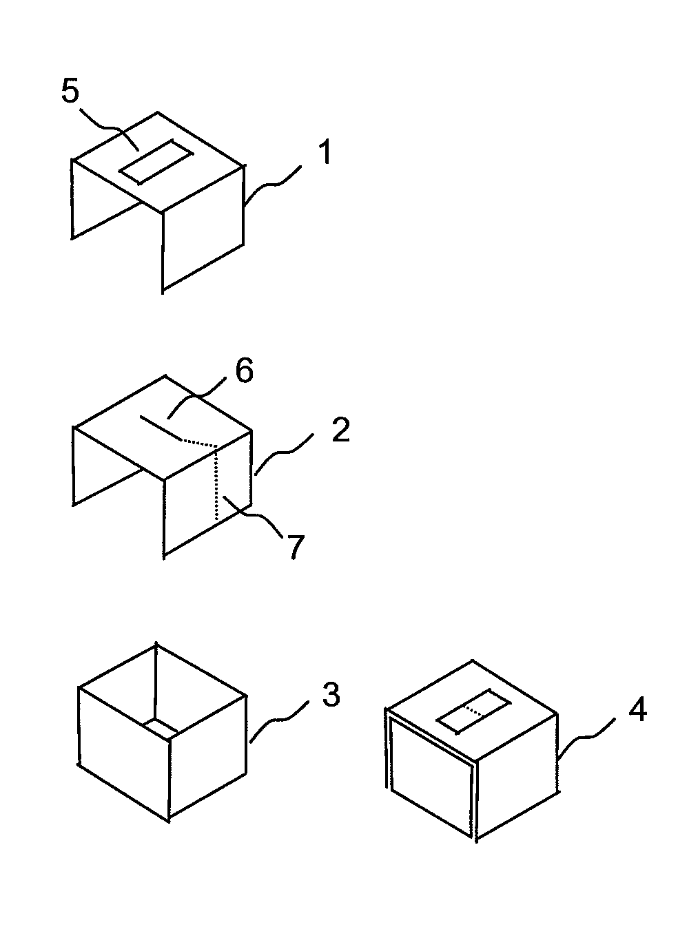
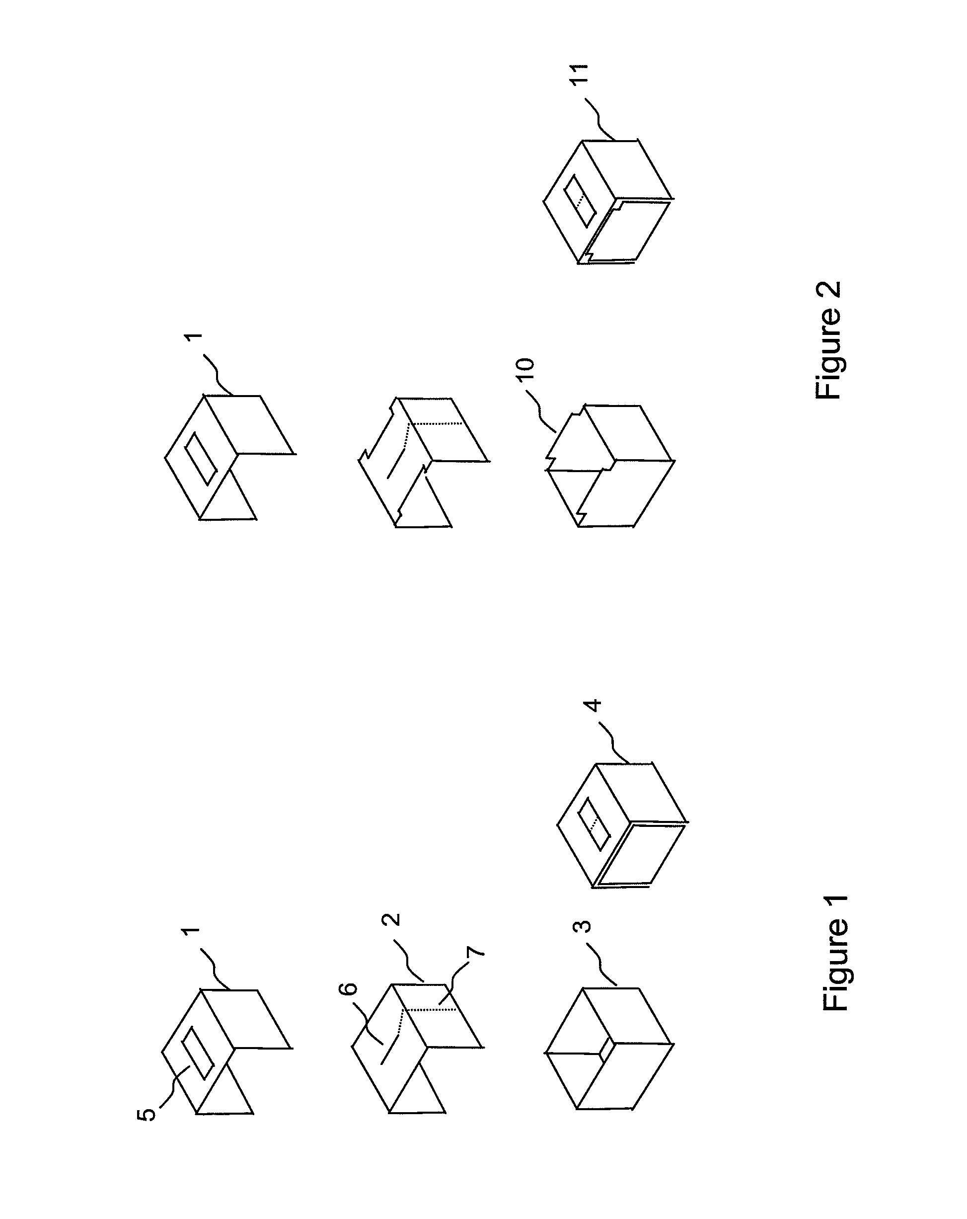
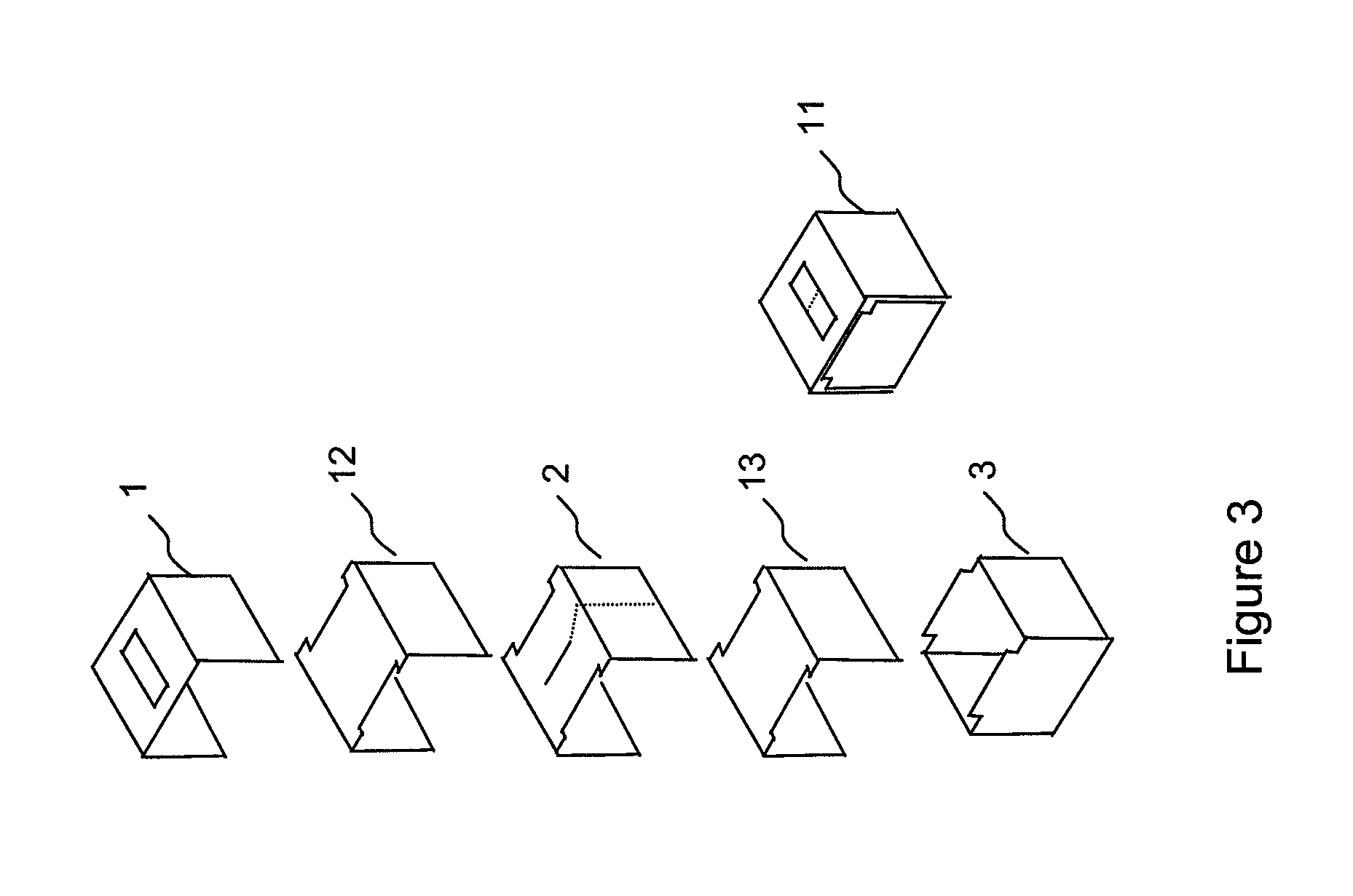
[0054]FIG. 1 illustrates a first embodiment of the invention, showing the construction of a single antenna element 4. An electrically conductive enclosure 3 such as a box structure comprises an open end so as to form an open cavity. An electrically conductive cover 1 is provided for the structure 3 and, when in position, the cover 1 covers the open end of the structure 3. The cover 1 can also partially or wholly cover one or two of the outer side walls of the structure. The cover has a slot 5 which is associated with the cavity of the structure 3. A feed layer ...


PUM


Abstract

Embodiments of the invention relate to an antenna structure and are particularly suited to array antennas. Conventionally, an antenna of the cavity-backed slot-radiating type comprises a slot formed in an end of an electrically conductive enclosure, which slot may be energised by a radiating element in registration with the slot. A feed network may connect to the radiating element via a transmission line formed by a conductive track on a feed layer located between the enclosure and an electrically conductive cover. A slot is formed in the section of the cover that covers the end of the cavity in which a slot is formed, such that the two slots are of substantially the same size and shape. A problem with this structure is that the cavity is difficult to mould in one piece and it can be difficult to achieve alignment of respective slots; as a result it is relatively costly to manufacture. Also, it is difficult to insert dielectric material into the enclosure to adjust the performance parameters of the antenna. An antenna according to an embodiment of the invention employs an enclosure having an aperture in one end; in preferred arrangements the aperture provides the enclosure with a substantially open end, over which the cover is placed. The cover has a slot therein, of a smaller size than the size of the aperture presented by the open ended enclosure and the slot in the cover then acts as the radiating slot. The benefit is that it is then easier to insert dielectric material into the enclosure and the enclosure is easier to mould in one piece, leading to a potential cost reduction.

Description

FIELD OF THE INVENTION[0001]The present invention relates to an antenna element and to an array of antenna elements, and is particularly, but not exclusively suited to cavity-backed, slot-radiating type.BACKGROUND OF THE INVENTION[0002]Modern wireless communications systems place great demands on the antennas used to transmit and receive signals, especially at cellular wireless base stations. Antennas are required to produce a carefully tailored radiation pattern with a defined beamwidth in azimuth, so that, for example, the wireless cellular coverage area has a controlled overlap with the coverage area of other antennas. The antennas may be deployed, for example, in a tri-cellular arrangement or, with a narrower beamwidth, as a six-sectored arrangement.[0003]In addition to a defined azimuth beam, such antennas are also required to produce a precisely defined beam pattern in elevation; in fact the elevation beam is generally required to be narrower than the azimuth beam.[0004]It is ...

Claims


Application Information

Patent Timeline
IPC IPC(8): H01Q13/18H01Q21/00
CPCH01Q13/18H01Q25/001H01Q21/08H01Q21/005H01Q13/0283
Inventor ADAMS, DAVIDURQUHART, ANDREWWADDOUP, WILLIAMKITCHENER, DEANHALL, STEVENGALE, SIMON
Owner APPLE INC
Why Eureka
Try Eureka