

Vehicle travel control system
- Summary
- Abstract
- Description
- Claims
- Application Information
AI Technical Summary
Benefits of technology
Problems solved by technology
Method used
Image

Examples
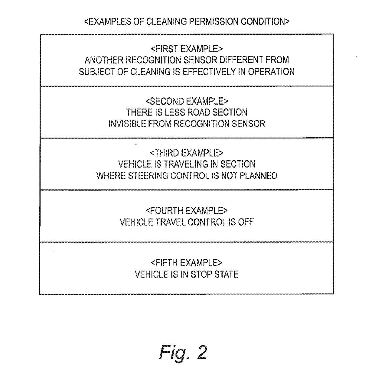
first example
3-1. First Example
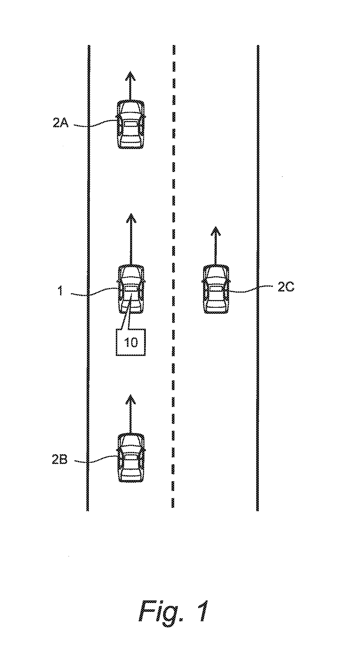
[0096]A first example of the cleaning permission condition is applied to a case where there are a plurality of recognition sensors 50. Here, let us consider a case where there are a first recognition sensor 50-1 and a second recognition sensor 50-2 as shown in FIG. 6. Types of the first recognition sensor 50-1 and the second recognition sensor 50-2 may be the same or different from each other.
[0097]For instance, the subject of cleaning is the first recognition sensor 50-1. In this case, the first example of the cleaning permission condition is that “the second recognition sensor 50-2 is effectively in operation”. Example of a method of determining that the second recognition sensor 50-2 is effectively in operation are as follows.
[0098]In FIG. 6, a same surrounding vehicle 2 is recognized by both the first recognition sensor 50-1 and the second recognition sensor 50-2. In other words, the surrounding vehicle 2 recognized by the first recognition sensor 50-1 is also ...
second example
3-2. Second Example
[0101]FIGS. 7 and 8 are conceptual diagrams for explaining a second example of the cleaning permission condition. Here, let us consider the recognition sensor 50 that recognizes a situation ahead of the vehicle 1. A recognition area RS is an area with a length L located ahead of the vehicle 1. For example, the length L corresponds to an effective recognition distance of the recognition sensor 50, and the recognition area RS corresponds to an effective recognition range of the recognition sensor 50.
[0102]In the example shown in FIG. 7, a road ahead of the vehicle 1 is straight. Therefore, a road in the recognition area RS is well recognized by the recognition sensor 50.
[0103]In the example shown in FIG. 8, on the other hand, a curved road exists ahead of the vehicle 1. A part of the road in the recognition area RS cannot be recognized by the recognition sensor 50. That is, in the recognition area RS, there is a road section invisible from the recognition sensor 50....
third example
3-3. Third Example
[0110]A third example of the cleaning permission condition is that “the vehicle 1 is traveling in a section where the steering control is not planned”. The steering control is generally executed in such situations as traveling in a curved road, making a lane change, and the like. Decrease in the recognition performance is not preferable in such the situation where the steering control is executed. On the other hand, in a section where the steering control is not planned, even when the recognition performance is temporarily decreased, its influence on the vehicle travel control is small.
[0111]Whether the steering control is planned or not can be recognized based on the vehicle travel plan for the vehicle travel control. The control device 100 refers to the vehicle travel plan to permit execution of the sensor cleaning processing in a section where the steering control is not planned. For example, when the vehicle 1 is traveling in a single lane straight road, execut...
PUM
 Abstract
Description
Claims
Application Information