Use of tetrafluoropropene based compositions

a technology of tetrafluoropropene and composition, which is applied in the direction of lubricant composition, heat exchange elements, chemistry apparatus and processes, etc., can solve the problems of deterioration of compressor lubrication, net loss of system efficiency, and relative large amount of refrigerant trapped in oil

Active Publication Date: 2019-09-19
ARKEMA FRANCE SA
View PDF2 Cites 12 Cited by
  • Summary
  • Abstract
  • Description
  • Claims
  • Application Information

AI Technical Summary

Problems solved by technology

However, due to good solubility of HFO-1234 in POE oils, a problem is found on heat transfer systems having an oil separator: a relatively large amount of refrigerant remains trapped by the oil.
This results in a net loss of efficiency

Method used


Image

  • Use of tetrafluoropropene based compositions
  • Use of tetrafluoropropene based compositions
  • Use of tetrafluoropropene based compositions

Examples


examples

[0301]Supplier of POE Triton SE 55 d Oil: FUCHS

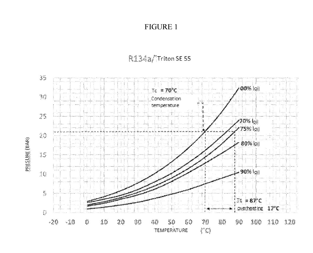
[0302]In an oil separator integrated in a screw compressor, the oil is recovered in the lower part of the separator. In this example, the amounts of refrigerant trapped by the oil in the separator are analysed.

[0303]The coolant / oil mixture in the separator is at a temperature Ts (which is also the temperature of the refrigerant at the outlet of the compressor) and the pressure in the separator is equal to the refrigerant vapour saturation pressure at the condenser inlet (Pcond). Therefore, this results in a system that works at a condensing temperature (Tcond), which is the saturation temperature of the refrigerant alone at the corresponding Pcond pressure.

[0304]In general, the analysis of a typical refrigerant / oil diagram (as shown for example in FIG. 1 for R134a) indicates that, at constant pressure (Pcond), the refrigerant concentration in the oil decreases when the temperature of the mixture (oil / refrigerant, Ts) increases and moves...


PUM


Abstract

The invention relates to the use of a composition comprising a polyol ester-based lubricant and a refrigerant F comprising at least one tetrafluoropropene and at least one hydrofluorocarbon, in a heat transfer system containing a vapour compression circuit comprising an oil separator.

Description

FIELD OF INVENTION[0001]The present invention relates to the use of a composition based on tetrafluoropropene and at least one lubricant, in refrigeration, air conditioning and heat pump.TECHNICAL BACKGROUND[0002]The problems posed by substances that deplete the atmospheric ozone layer were discussed in Montreal, where the protocol imposing a reduction in the production and use of chlorofluorocarbons (CFCs) was signed. This protocol has been amended to eliminate the use of CFCs and extend the regulation to include other products, including hydrochlorofluorocarbons (HCFCs).[0003]The refrigeration and air-conditioning industry has invested heavily in the substitution of these refrigerants and hydrofluorocarbons (HFCs) have thus been marketed.[0004]In the automotive industry, the air conditioning systems of vehicles marketed in many countries have moved from a chlorofluorocarbon (CFC-12) refrigerant to hydrofluorocarbon (1,1,1,2-tetrafluoroethane: HFC-134a) refrigerant, less harmful fo...

Claims


Application Information

Patent Timeline
IPC IPC(8): C10M171/00C09K5/04
CPCC10M2207/2835C09K2205/126C10M171/008C10N2220/302C09K2205/128C09K5/045C10N2240/30C09K2205/22C10N2020/101C10N2040/30C10N2070/00F25B9/002
Inventor RACHED, WISSAM
Owner ARKEMA FRANCE SA
Why Eureka
Try Eureka