
Lightweight molded cover

a technology of molded covers and covers, applied in the field of covers, can solve the problems of not supporting one or both ends of each cover, plates with sufficient thickness to support vehicle traffic, and large spans, etc., and achieve the effect of high r-value materials

Pending Publication Date: 2019-09-19
HUBBELL INC
View PDF8 Cites 7 Cited by
  • Summary
  • Abstract
  • Description
  • Claims
  • Application Information

AI Technical Summary

Benefits of technology

The present disclosure provides a method for making a cover for underground structures and a cover that can be used for various purposes such as trench cover, vault cover, manhole cover, and road plate. The method involves placing a mold cavity, adding an edge reinforcement layer, a top reinforcement layer, and a core in the mold cavity. A polymer mix is then introduced into the mold cavity and the introduction process can include injection molding, vacuum bag molding, or resin transfer molding. The cover made using this method has a layered structure with strong edge and bottom reinforcements that provide durability and stability. The cover also has a high R-value to provide thermal insulation. The technical effects of this patent include improved durability and stability of underground structures and better protection from environmental factors.

Problems solved by technology

Because the cover is flush with the ground, it may be subject to heavy loads, such as when a vehicle drives over the cover.
Plates with sufficient thickness to support vehicle traffic and that are large enough to span holes necessary to repair underground structures are heavy, usually requiring motorized equipment such as a back hoe, to deliver, install, and remove them.
One or both ends of each of the covers is usually not supported, since any support structure spanning the top of the trench might interfere with cables, conduits, and pipes being dropped into the trench.
This adds cost and complexity to the task of servicing equipment in the vault or trench.

Method used


Image

  • Lightweight molded cover
  • Lightweight molded cover
  • Lightweight molded cover

Examples


Embodiment Construction

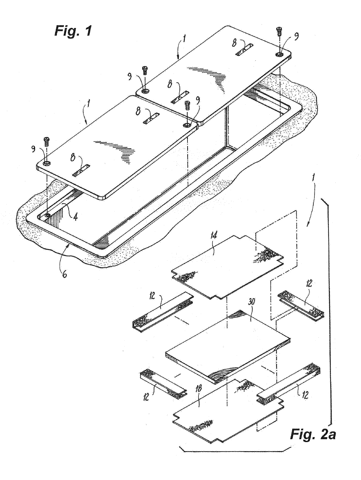
[0024]FIG. 1 shows a trench lined with a trench liner 6 and covered with covers 1 according to an embodiment of the disclosure. Trench liner 6 is designed to be installed below ground, for example, beneath a roadway, a sidewalk, or a lawn with the cover 1 flush with the ground surface. The top edges of the trench liner 6 include shoulders 4. One or more trench covers 1 are adapted to fit over the trench with their respective edges supported by shoulders 4. According to one aspect of the disclosure, instead of being supported by shoulders, cover 1 spans the trench and is supported by the ground surface on either side of the trench. Cover 1 may include lifting handles or lifting pins 8.

[0025]Bolts may be provided in bolt holes 9 to secure cover 1 onto collar 4. Bolts may have a security feature such as a head requiring a specialized tool, for example, a pentagonal shape, to discourage unauthorized persons from tampering with the vault or its contents. Cover 1 may have a textured top s...


PUM

PropertyMeasurementUnit
densityaaaaaaaaaa
densityaaaaaaaaaa
apparent densityaaaaaaaaaa

Abstract

Disclosed is a cover for a utility vault and a method for making such covers. The cover is formed from fiberglass reinforcement layers, a low-density core, and a polymer mix matrix. The reinforcement layers include a bottom reinforcement layer, one or more edge reinforcement layers, and a top reinforcement layer. A first portion of the edge reinforcement layer overlaps a portion of the bottom reinforcement layer and a second portion of the edge reinforcement layer overlaps a portion of the top reinforcement layer. The core is positioned between the top and bottom reinforcement layers. The reinforcement layers are formed from fiberglass fabric and may include fiberglass layers whose fibers are oriented quadraxially. The polymer mix impregnates the fabric layers, encases the core, and binds the components together. The polymer matrix includes a thermoset polymer resin.

Description

[0001]This application claims priority under 35 U.S.C. § 119 to U.S. Provisional Patent Application No. 62 / 643,532, filed on Mar. 15, 2018. The disclosure of that application is incorporated herein by reference.BACKGROUNDField[0002]The present disclosure relates to covers for utility vaults, trenches, and other in-ground structures and to methods for forming such covers. More particularly, the present disclosure relates to lightweight covers formed from a lightweight core, fiberglass reinforcements, and a polymer matrix and methods for forming such covers.Description of the Related Art[0003]Equipment for utilities, such as transformers, switches, control panels, and valves are often housed in vaults located underground. Such vaults include an opening at the top to allow workers to access the equipment either by reaching down through the opening, or for larger vaults, allowing workers to descend into the vault. The opening must be covered to protect the equipment from weather and fro...

Claims


Application Information

Patent Timeline
Patent Type & Authority Applications(United States)
IPC IPC(8): E02D29/14B29C70/48B29C70/54B32B27/12B32B27/36B32B27/20B32B3/08
CPCB29K2509/08B32B3/08B29C70/546E02D29/1472E02D2300/0071E02D29/1454B29L2031/724E02D2300/0006B29K2309/08B29K2995/0063E02D2250/0007B32B27/20B32B2264/101E02D2200/1628B29K2067/06B32B2307/72B32B2262/101E02D2300/0046E02D2300/0075E02D2300/0026B29C70/48B32B27/36B32B27/12B29C70/443B29C70/865B32B2419/00B32B2262/103B32B27/40B32B2260/046B32B3/18B32B21/10B32B5/12B32B5/245B32B15/20B32B9/047B32B2262/02B32B5/06B32B2250/03B32B2264/102B32B2250/40B32B27/32B32B5/18B32B2260/023B32B2264/104B32B9/005B32B5/16B32B21/02B32B21/14B32B15/14B32B2264/107B32B3/12B32B2307/718B32B5/30B32B2266/0228B32B2260/025B32B2264/108B32B5/26Y10T428/24785B32B5/02Y10T428/24124
Inventor FAGAN, LEMUEL DAVIDCHUDLEY, KEITH ALDENFORSTEN, ERNEST STEPHENESTES, JASON DAVID
Owner HUBBELL INC
Learn More