
Metallic pipe connection

Active Publication Date: 2019-09-19
GIACOMINI
View PDF0 Cites 0 Cited by
  • Summary
  • Abstract
  • Description
  • Claims
  • Application Information

AI Technical Summary

Benefits of technology

The patent describes a connection system for pipes that has several advantages. First, it allows for better deformation when pliers are used to press on the outer surface of the connection. Second, the connection can be used with different materials, making it more versatile and flexible. Third, the connection improves manufacturing efficiency and smoothly removes any rough edges. The connection system also has a unique design that allows for controlled and uniform deformation, and avoids weakness points or cracks during installation.

Problems solved by technology

This results in a reduced versatility of such types of connections since—if products of different manufacturers are desired to be used—it would be necessary to have tools (or pliers) suitable for each geometry.
In order to overcome such drawback, solutions have been found over time wherein only one tool is usable for different geometries, even if versatility is not complete, since such tools cannot be used generally for all the available geometries, but only for some of them.
Another drawback, in the practice, is that O-rings are not always homogeneously pressed by the deformation of the metal, with the risk of leakages or failures of O-rings.
A common drawback of known solutions is the fact that, due to the same operating principle, residual stresses are inevitably generated after the deformation due to pressing by pliers.
Such residual deformations cause the structure of the fitting to weaken and can trigger crack or leak forming processes, resulting in easily conceivable consequences.

Method used


Image

  • Metallic pipe connection
  • Metallic pipe connection
  • Metallic pipe connection

Examples


Embodiment Construction

[0032]While the invention is susceptible of various modifications and alternative forms, some preferred embodiments are shown in the drawings and will be described below in details.

[0033]It should be understood, however, that there is no intention to limit the invention to the specific embodiment disclosed, but, on the contrary, the intention of the invention is to cover all modifications, alternative constructions and equivalents falling within the scope of the invention as defined in the claims. The use of “for example”, “etc”, “or” indicates non-exclusive alternatives without limitation, unless otherwise defined. The use of “includes” means “includes, but not limited to,” unless otherwise defined. Terms as “vertical” and “horizontal”, “upper” and “lower” (with no other indications) have to be read with reference to the assembling (or operating) conditions and with reference to the standard terminology in use in common speech, where “vertical” means a direction substantially paral...


PUM


Abstract

A metallic pipe connection may comprise a tubular body and a terminal tubular engagement portion configured to be engaged on a pipe and to be fixed thereto by means of plastic deformation of the engagement portion, and a terminal flange on the opposite side of the tubular body with respect to that one provided with the tubular engagement portion. The tubular engagement portion may include an annular seat for a sealing gasket, having a first housing groove for the sealing gasket which may be internally open towards the tubular engagement portion, and at least part of the tubular engagement portion and the annular seat may be plastically deformed such to generate a mechanical seal on the pipe on which the tubular engagement portion is fitted.

Description

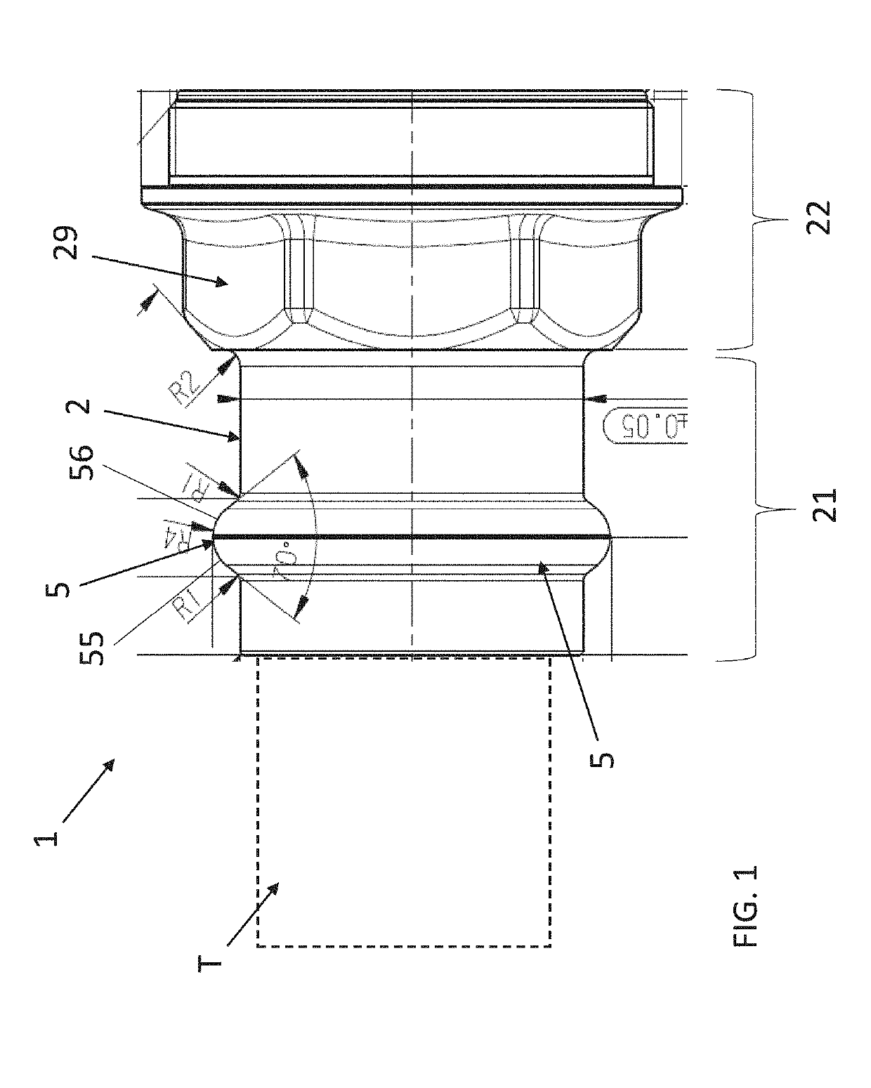
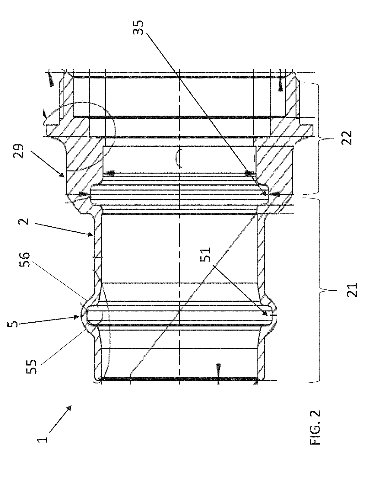
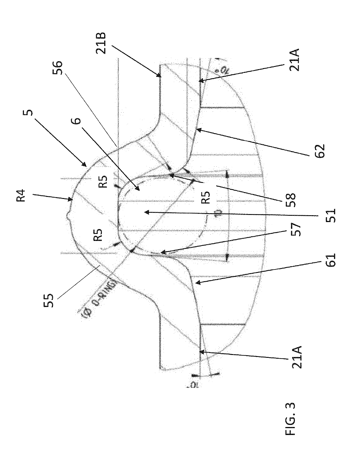
CROSS REFERENCE TO RELATED APPLICATIONS[0001]This is a national state application under 35 U.S.C. § 371 of PCT patent application PCT / IB2017 / 056922, filed on Nov. 6, 2017, which claims the benefit of IT 102016000120936, filed on Nov. 29, 2016, each of which is hereby incorporated by reference in its entirety.TECHNICAL FIELD[0002]The present invention relates to the field of metallic pipe connections, particularly in hydraulic industry, and more specifically to connections made by plastically deforming one or both parts being connected.PRIOR ART[0003]Several types of watertight connections between flanges, pipes, fittings and the like in hydraulic industry are known from prior art. One of such types provides to locally plastically deform one or both parts that have to be connected, typically by applying a suitable force, for example by means of a pliers deformation tool, such as described in prior art document published as EP1223008, that can be electrically powered, or more simply, ...

Claims


Application Information

Patent Timeline
IPC IPC(8): F16L13/14
CPCF16L13/142F16L13/141F16L17/02
Inventor ALBERGANTI, GIACOMORUGA, GIULIANO
Owner GIACOMINI
Learn More