Method and apparatus for pre-spinning rotor forgings

a technology of rotor forging and pre-spinning process, which is applied in the direction of weighing apparatus for materials with special properties/forms, fluid pressure measurement by mechanical elements, special data processing applications, etc., can solve the problems of affecting the clearance between the rotor and the surrounding casing, the rotor may undetectedly expand, and the conventional pre-spinning process is a time-consuming and costly process, so as to prevent over-spinning and relieve the residual stress of forging

Active Publication Date: 2010-08-26
GENERAL ELECTRIC CO
View PDF31 Cites 51 Cited by
  • Summary
  • Abstract
  • Description
  • Claims
  • Application Information

AI Technical Summary

Benefits of technology

[0011]An exemplary method for pre-spinning a rotor forging to relieve forging induced residual stresses in the rotor forging includes, mounting the rotor forging on a pre-spin machine of a pre-spinning system, balancing the pre-spin machine with the rotor forging mounted thereon at a first rotational speed, and pre-spinning the rotor forging while mounted on the pre-spin machine at a second rotational speed substantially greater than the first rotational speed. Using a one per rev sensor for determining a weight placement angle for the balancing of the pre-spin machine with the rotor forging mounted thereon. Using a vibration sensor for determining an amount of weight to add to a spinning assembly including the rotor forging during the balancing. Placing one or more balance weights on an inside surface of the rotor forging or elsewhere on a spinning assembly of the pre-spinning system during the balancing wherein the spinning assembly includes the rotor forging. Using balance weights made of a high-density non-metallic material placed on the inside surface with an adhesive.
[0012]A more particular embodiment of the method for pre-spinning further includes the second rotational speed being about an order of magnitude greater than the first rotational speed and more particularly the first rotational speed being in a first rotational speed range between about 100 RPM to 1200 RPM and the second rotational speed being in a second rotational speed range between about 5,000 RPM to 18,000 RPM.
[0013]An exemplary method for preventing over spinning includes first determining rotational inertia of a spinning assembly including the rotor forging during a spin up period of the pre-spinning by determining a rate of rotational acceleration vs. torque applied to the spinning assembly and checking the determined rotational inertia against a pre-determined rotational inertia value for the rotor forging. Then stopping the pre-spinning and / or providing the operator with an error message if during the checking the determined rotational inertia exceeds the pre-determined rotational inertia value for the rotor forging.
[0014]A pre-spinning system includes a pre-spin machine operable for relieving forging induced residual stresses in a rotor forging, a one per rev sensor for determining a weight placement angle for balancing the pre-spin machine, a vibration sensor to determine an amount of weight to add for balancing the pre-spin machine, a control means for balancing the pre-spin machine and controlling the pre-spin machine during pre-spinning, and the control means operably connected to the vibration and one per rev sensors for receiving signals from the sensors. In a more particular embodiment of the system the pre-spin machine is operable to spin in a rotational speed range between about 5,000 RPM to 18,000 RPM.
[0015]An exemplary embodiment of the system further includes the control means having a first controller operable for controlling and displaying rotor speed and vibration level of the pre-spin machine during pre-spinning and a second controller operable for balancing the pre-spin machine before pre-spinning, the first controller being operably connected to the vibration sensor, and the second controller being operably connected to the vibration sensor and one per rev sensors. The rotor forging is mounted to a spindle of the pre-spin machine and one or more balance weights are mounted on an inside surface of the rotor forging or elsewhere on the spinning assembly. The one or more balance weights are made of a high-density non-metallic material stuck on the inside surface of the rotor forging or elsewhere on the spinning assembly with an adhesive.
[0016]In another more particular embodiment of the system, the one per rev sensor includes a static pickup co-operable with a rotatable trigger connected to a spindle of the pre-spin machine. The spinning assembly may include a spin arbor connected to a spindle of the pre-spin machine and rotor forging mounted to the spin arbor by a fixture.

Problems solved by technology

Residual stresses from a metal alloy forging process used in fabricating turbine disks in the engine may relieve during engine operation, such that the turbine disks may undesirably expand.
Such disk expansion may adversely affect clearances between the rotor and surrounding casing during engine operation.
Conventional pre-spinning processes is a time consuming and costly process.
Moreover, because the high rotational speeds are needed to relieve the residual stresses the rotor forging and its mounting fixture must be balanced which increases the complexity of the pre-spin process.
Pre-spin machines are not designed to balance a part, typically they just spin parts to high speeds and are designed to spin parts fast enough for the part to actually fail.
If not, reaching proper high speeds may not be attainable.
This problem then creates significant cost prior to even pre-spinning the rotating part.
Another problem relates to the wear of the pre-spin machine over time for rotating parts still having high vibration levels.
This may cause premature failure of specific components or excessive preventative maintenance costs to prevent these failures.
Failure within the pre-spin machine can cause significant damage to the rotating part, fixture, spindle, and machine.
Yet another problem with having high unbalance and vibration in the pre-spin machine is the potential for the rotating part to shift within the fixture causing higher vibration during deceleration than during the acceleration to top pre-spin speed.
This concern can also cause premature machine failure and rotating part damage.

Method used


Image

  • Method and apparatus for pre-spinning rotor forgings
  • Method and apparatus for pre-spinning rotor forgings
  • Method and apparatus for pre-spinning rotor forgings

Examples


Embodiment Construction

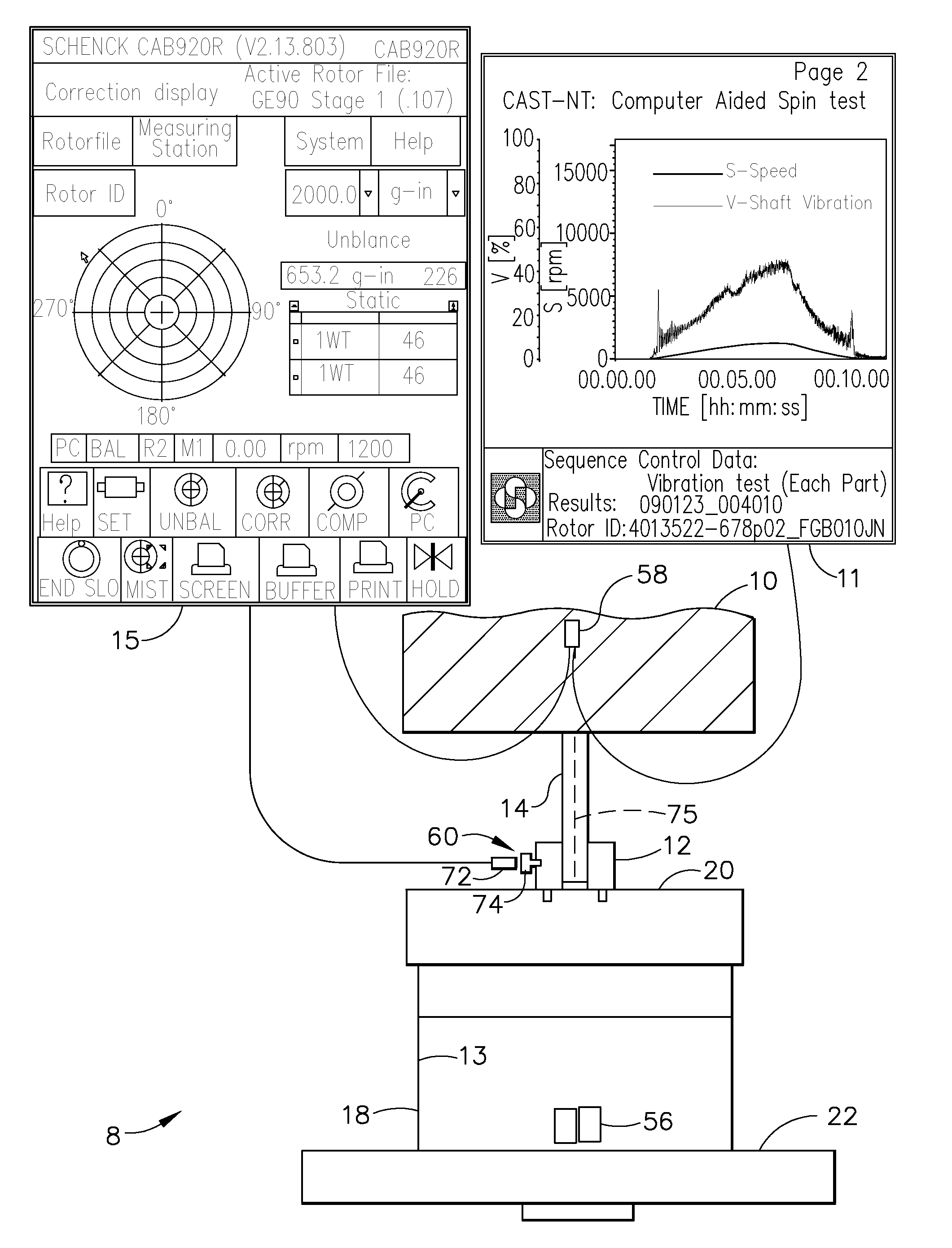
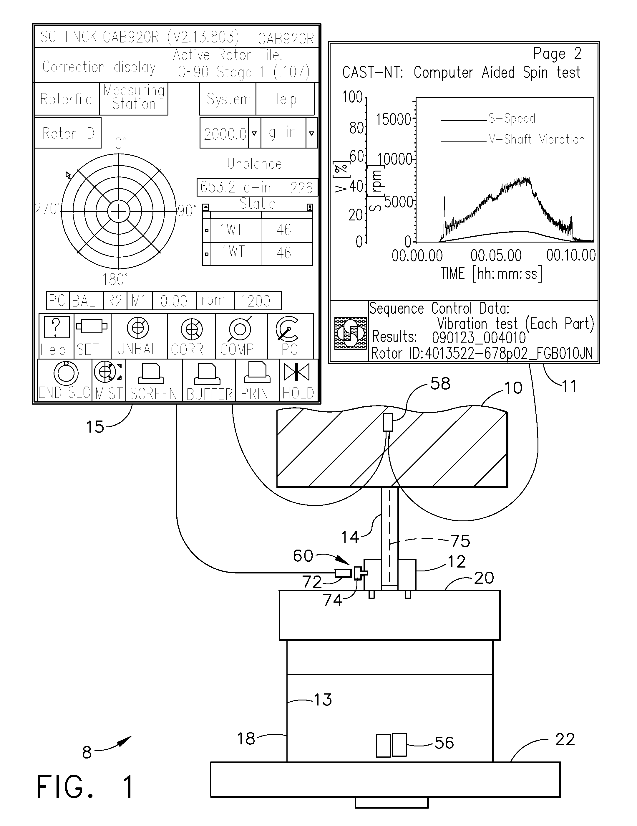
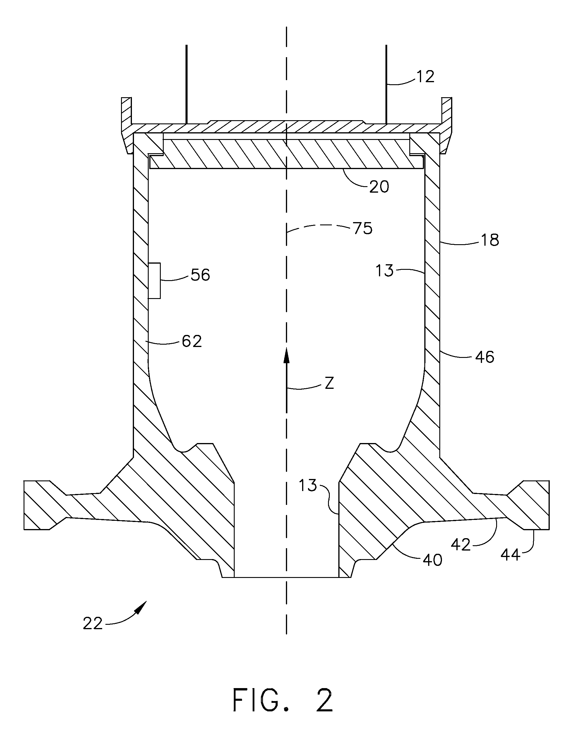
[0027]Illustrated in FIG. 1 is a pre-spinning system 8 including an exemplary pre-spin machine 10 having a spin arbor 12 connected to a spindle 14 of the pre-spin machine 10. The spindle 14 has an axis 75 of rotation, is vertically oriented, and is held at some distance from an annular rotor forging 18 as is well known in the art. The spin arbor 12 is attached to a fixture 20 for holding the rotor forging 18 which has an axial bore 13 illustrated in cross-section in FIG. 2. The pre-spin machine 10 includes at least one controller (two are illustrated herein).

[0028]The pre-spin machine 10 illustrated herein is unique because it is designed to and is capable of both spinning rotor forgings to very high rotational speeds in ranges between 5,000 RPM to 18,000 RPM in order to relieve forging induced residual stresses in the rotor forgings and balance a spinning assembly 22 which includes the rotor forging 18, spindle 14, spin arbor 12, and the fixture 20 while they are attached to the pr...


PUM

PropertyMeasurementUnit
residual stressesaaaaaaaaaa
rotational speedaaaaaaaaaa
weightaaaaaaaaaa

Abstract

A method and system for relieving forging induced residual stresses in a rotor forging balances a pre-spin machine with the forging mounted thereon at a first rotational speed and then pre-spins the forging with it mounted on the machine at a substantially greater second rotational speed. A one per rev sensor is used for determining a weight placement angle and a vibration sensor is used for determining an amount of weight to add to a spinning assembly including the forging during the balancing. High-density non-metallic balance weights adhesively attached on an inside surface of the forging or spinning assembly may be used. The rotational inertia of the spinning assembly may be checked during a spin up period by determining a rate of rotational acceleration vs. torque applied to the spinning assembly and used to stop the pre-spinning if it is to great.

Description

BACKGROUND OF THE INVENTION[0001]1. Technical Field[0002]This invention relates to methods and machines for manufacturing rotors from forging and, more particularly, to pre-spinning rotor forgings to relieve forging induced residual stresses.[0003]2. Background Information[0004]During normal operations gas turbine engines may operate with high rotational speeds and relatively high temperatures. Residual stresses from a metal alloy forging process used in fabricating turbine disks in the engine may relieve during engine operation, such that the turbine disks may undesirably expand. Such disk expansion may adversely affect clearances between the rotor and surrounding casing during engine operation.[0005]In order to reduce occurrences and degree of disk expansion, at least some known engine disks are spun during the manufacturing process in a near-finished condition to relieve the residual stresses in the disk or other rotor forging. This process is known as pre-spinning of the disks g...

Claims


Application Information

Patent Timeline
Patent Type & Authority Applications(United States)
IPC IPC(8): G01M1/16G01L1/00G01N29/04G01P3/00G01G9/00
CPCF01D5/027F05D2260/941Y02T50/671G01M1/32G01M1/22Y02T50/60
Inventor ALLEN, JEFFREY SCOTTKESECKER, ROBERT LYNNGROOMS, JAMES HAMILTON
Owner GENERAL ELECTRIC CO
Why Eureka
Try Eureka