Interconnection system

a technology of interconnection system and printed circuit board, which is applied in the direction of coupling device connection, optical element, instrument, etc., can solve the problems of conductive traces on printed circuit board having their own limitations for high speed high frequency signal transmission

Active Publication Date: 2019-09-26
FOXCONN (KUNSHAN) COMPUTER CONNECTOR CO LTD +1
View PDF0 Cites 11 Cited by
  • Summary
  • Abstract
  • Description
  • Claims
  • Application Information

AI Technical Summary

Problems solved by technology

Anyhow, conductive traces on the printed circuit board have their

Method used


Image

  • Interconnection system
  • Interconnection system
  • Interconnection system

Examples


Embodiment Construction

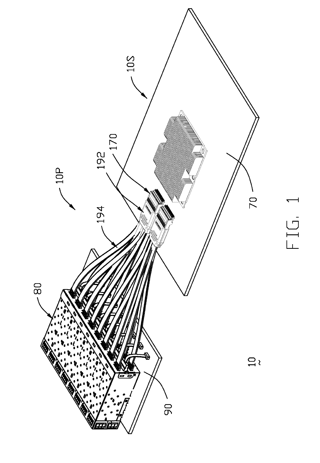
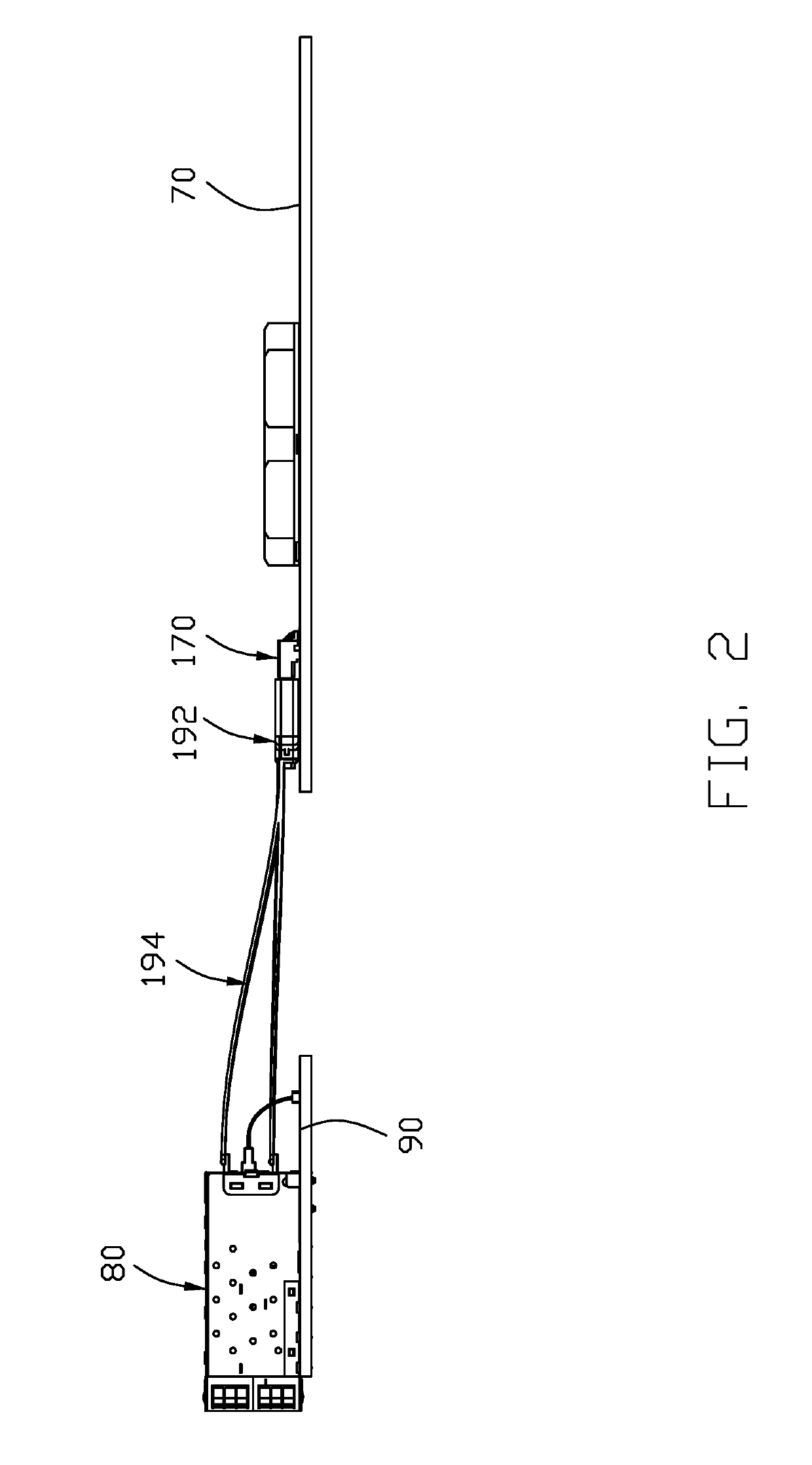
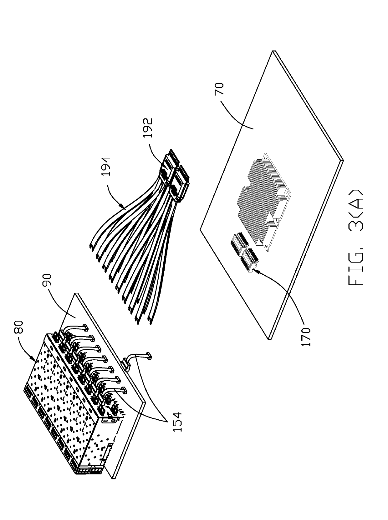
[0085]Reference will now be made in detail to the preferred embodiment of the present invention. Referring to FIGS. 1 to 22, generally speaking an electrical assembly 10 is composed of a system side 10S and a periphery side 10P linked to each other. The periphery side 10P includes a printed circuit board 90, a metallic cage structure 80 mounted and a plurality of cable receptacle connectors 100 both mounted upon the printed circuit board 90 wherein each of the cable receptacle connectors 100 is located at a rear portion of the corresponding individual receiving space formed in the cage structure 80.

[0086]The cage structure 80 includes a U-shaped main body 81, a bottom cover 82 and a rear cover 83 assembled together. The main body 81 includes a top wall 84 and two side walls 85. A gasket 86 is attached upon a front end of the main body 81 and the bottom cover 82. A plurality of dividers 87 are assembled within a room in the assembled main body 81 and the bottom cover 82 in a parallel...


PUM


Abstract

An electrical receptacle connector is mounted within a metallic cage for mating with a QSFP module received within the cage. The contacts of the cable receptacle connector are arranged with two groups, of which one are connected to the printed circuit board on which the cage is mounted, and the other are connected to the wires which are further connected to a board-mount receptacle connector mounted on another printed circuit board on which the CPU (Central Processing Unit) socket is mounted. Each board-mount receptacle connector corresponds to more than one cable receptacle connector.

Description

[0001]The present invention relates to an electrical connector assembly, especially to the receptacle connector equipped with cable to transmit high speed signal instead of mounting to PCB by following the spirit of the previous designs of which the provisional applications have Ser. Nos. 62 / 367,098 filed on Jul. 26, 2016, 62 / 399,272 filed on Sep. 23, 2016, 62 / 412,841 filed on Oct. 26, 2016, 62 / 425,627 filed on Nov. 23, 2016, 62 / 449,133 filed on Jan. 23, 2017, 62 / 509,141 filed on May 21, 2017, 62 / 522,113 filed on Jun. 20, 2017, 62 / 533,131 filed on Jul. 17, 2017, 62 / 584,751 filed on Nov. 11, 2017, 62 / 614,366 filed on Jan. 6, 2018, and 62 / 635,508 filed on Feb. 26, 2018.BACKGROUND OF THE INVENTION1. Field of the Invention2. Description of Related Arts[0002]A traditional design between the receptacle connector, which is located at the rear end of the cage for coupling with a QSFP or other type module, and a CPU is through the traces on the printed circuit board on which the CPU socket i...

Claims


Application Information

Patent Timeline
IPC IPC(8): G02B6/43H01R12/72H01R13/6587H01R27/02H01R25/00G02B6/38
CPCH01R12/721G02B6/43H01R27/02H01R13/6587H01R25/003G02B6/3897H01R12/716H01R12/722H01R13/502H01R12/712H01R13/514H01R13/7172
Inventor LITTLE, TERRANCE F.
Owner FOXCONN (KUNSHAN) COMPUTER CONNECTOR CO LTD
Why Eureka
Try Eureka