
Method for detecting and recognizing long-range high-density visual markers

a high-density, visual marker technology, applied in the direction of redundant data error correction, fault response, instruments, etc., can solve the problems of poor lighting of the area, inconvenient capture of markers from long distances or in unfavourable optic conditions, and greater difficulties

Active Publication Date: 2019-09-26
UNIV DE ALICANTE
View PDF0 Cites 4 Cited by
  • Summary
  • Abstract
  • Description
  • Claims
  • Application Information

AI Technical Summary

Benefits of technology

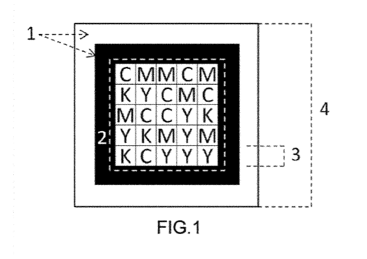
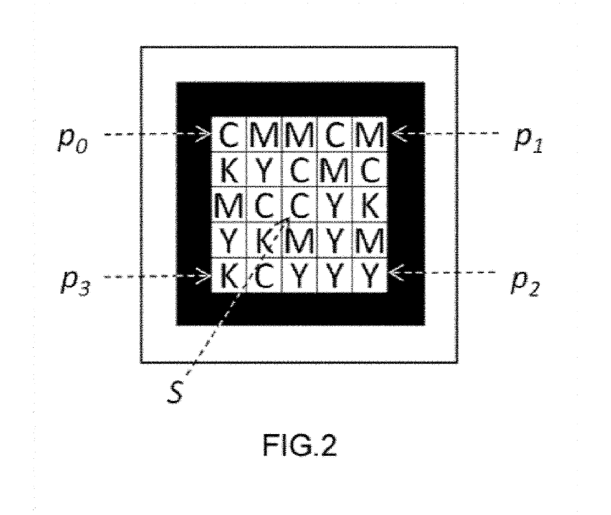
The patent text describes a method for designing a marker that can be easily identified and labeled, regardless of its rotation. The marker is made up of four corner colors, which are the darkest elements in the color palette. This palette is used to identify and label the rest of the data grid by using a color proximity criterion. The technical effect of this method is the creation of a robust marker that can be easily identified and labeled, even in situations where the marker is rotated.

Problems solved by technology

In other words, these markers are not suitable for being captured from long distances or in unfavourable optic conditions, such as poor lighting of the area, blurring due to sudden camera movements, among others.
In this last case, the colour provides more dense information, but it is also the source of greater difficulties when it comes to reading the code, since the user must correctly centre the marker in an area of the image so that the algorithm may correctly capture it.
Markers of this type usually hold much less information than dense markers because when information is added, the geometry of the marker becomes more complicated, seriously affecting its detection from a distance.

Method used


Image

  • Method for detecting and recognizing long-range high-density visual markers
  • Method for detecting and recognizing long-range high-density visual markers
  • Method for detecting and recognizing long-range high-density visual markers

Examples


example 1

f the Method

[0064]To assure the correct operation of the markers and the detection method proposed in the present invention, a functional prototype has been developed which consists of two applications: a marker generator and detector. Both applications have been developed in C++ in the high-performance cross-platform programming environment Qt SDK (http: / www.qt-project.org).

[0065]The generator manages a marker database with the information of each marker (marker code, text associated with the marker, real print size, etc.) and allows to create, remove, search for, and print these markers with the selected physical size.

[0066]Furthermore, the detector is in charge of detecting the markers on the images obtained from the camera of the device. In this case, it has been developed both for Android and iOS devices. When a marker is detected, the system queries its code in the database and vocalises (using Text To Speech) its content. Furthermore, it also vocalises the real distance at wh...


PUM


Abstract

The proposal relates to a complete system of long-range, high-density visual markers (marker design and detection method). In the design, a conventional location system for the long-range markers is used. The proposal therefore focuses on a system for coding information, which in this case is a colour-based code having four states, duplicating the code density with respect to conventional black-and-white systems. Moreover, the detection method requires very few computational resources, making it very efficient and especially suitable for mobile devices. To a great extent, the success of the technique lies in the methods proposed for the treatment of the colour.

Description

OBJECT OF THE INVENTION[0001]The object of the present invention is an efficient system of long-range, high-density visual markers. The present invention presents a new type of visual markers and a method for detecting and recognising them by means of the camera of a mobile device, for the purpose of being used as a guide for the visually impaired.STATE OF THE ART[0002]An artificial marker is an element which is intentionally introduced in a scene and contains some type of information in order to label or signal it. When the marker is configured so that its information is captured and interpreted through the digital camera of a portable electronic device (e.g. a smartphone or tablet), the marker is referred to as a “visual marker”. Unlike other one-dimensional markers, such as barcodes, visual markers usually provide information in a two-dimensional form.[0003]When a visual marker is conceived to hold a large amount of information, it is referred to as a dense marker. To hold said i...

Claims


Application Information

Patent Timeline
Patent Type & Authority Applications(United States)
IPC IPC(8): G06K19/06G06F11/10G06T3/40
CPCG06F11/1004G06K19/0614G06T3/4007G06K2019/06225G06K19/06037G06T11/001
Inventor SAEZ MARTÍNEZ, JUAN MANUELESCOLANO RUIZ, FRANCISCOLOZANO ORTEGA, MIGUEL ÁNGELPITA LOZANO, JAVIER
Owner UNIV DE ALICANTE
Learn More