
Battery pack

Active Publication Date: 2019-09-26
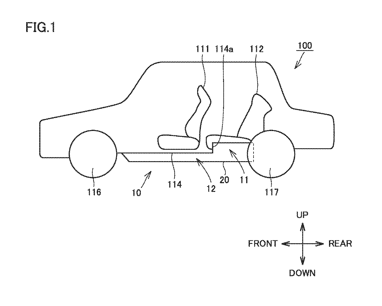
TOYOTA JIDOSHA KK
View PDF1 Cites 2 Cited by
  • Summary
  • Abstract
  • Description
  • Claims
  • Application Information

AI Technical Summary

Benefits of technology

The present invention provides a battery pack that can prevent damage to multiple cell stacks in a housing case caused by shocks or impacts. The battery pack includes a support member that helps to distribute shocks and impacts, reducing the likelihood of damage. The battery pack also ensures sufficient space between the cell stacks to prevent interference and collision between them, even in cases of deformation. Overall, the invention improves the reliability and safety of battery packs used in various applications.

Problems solved by technology

In such a case, the bracket disclosed in Japanese Patent Laying-Open No. 2011-218910 has difficulty in sufficiently suppressing collision between the rear suspension and the housing case.
When the rear suspension collides with the housing case, it is concerned that shock is transmitted to a plurality of cell stacks housed in the housing case.
In this case, the cell stacks may be broken in some cases.

Method used


Image

  • Battery pack
  • Battery pack
  • Battery pack

Examples


case 22

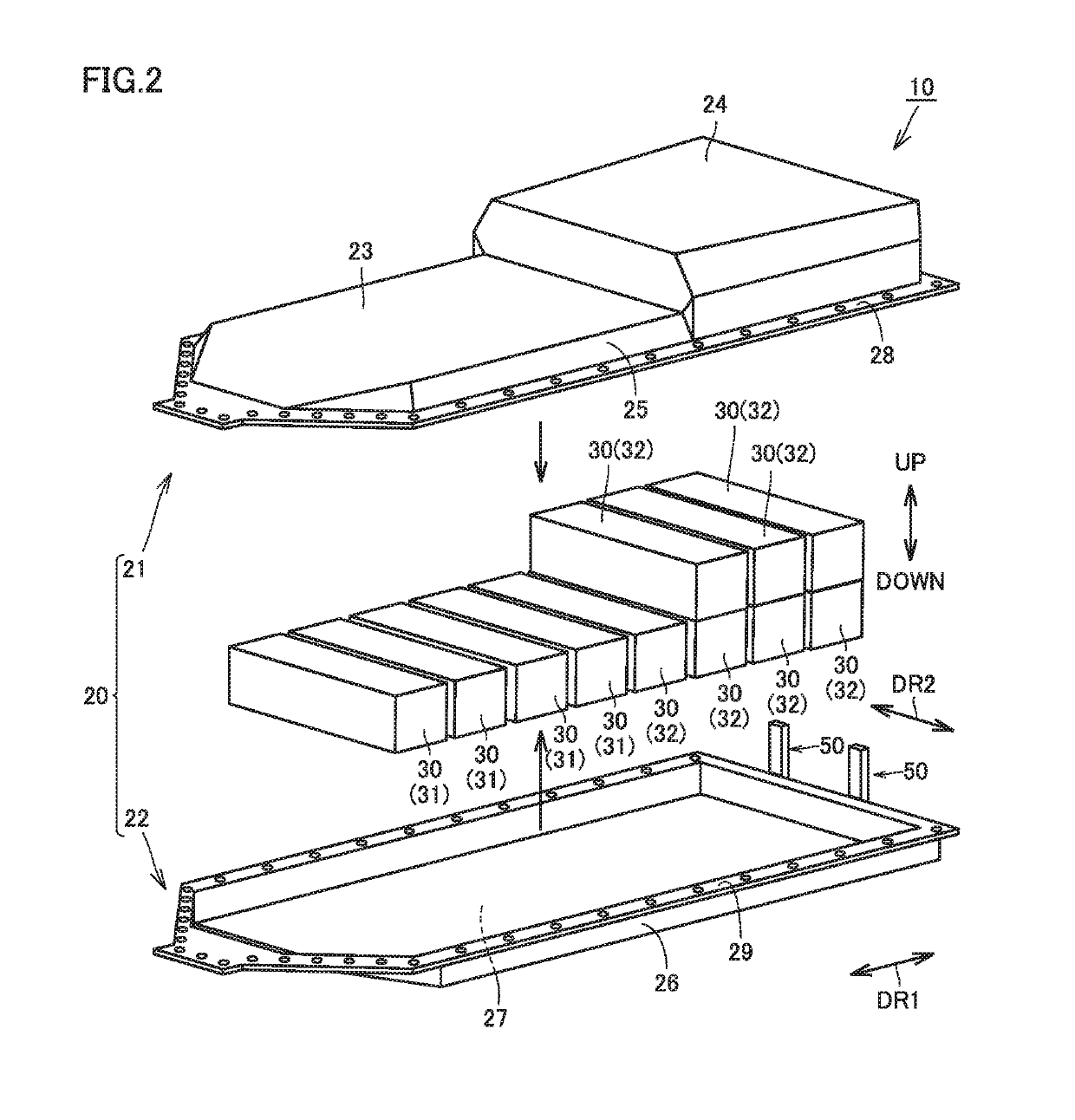
[0038]Lower case 22 has a box shape that is open upwardly. Lower case 22 has bottom portion 27 described above, a sidewall portion 26 and a flange portion 29. Bottom portion 27 is provided to face ceiling portion 23 in the up-down direction. Sidewall portion 26 is provided to extend upwardly from an outer peripheral edge of bottom portion 27. Sidewall portion 26 forms a sidewall of housing case 20, together with sidewall portion 25 of upper case 21. Flange portion 29 extends from an upper end of sidewall portion 26 to the outside of housing case 20, thereby forming a flange shape.

[0039]With flange portion 28 and flange portion 29 being stacked in the up-down direction, flange portion 28 and flange portion 29 are fastened by a plurality of fastening members (not shown). As a result, upper case 21 and lower case 22 are integrally coupled to each other and form a space for housing the plurality of cell stacks 30.

[0040]The plurality of cell stacks 30 include a plurality of first cell st...


PUM


Abstract

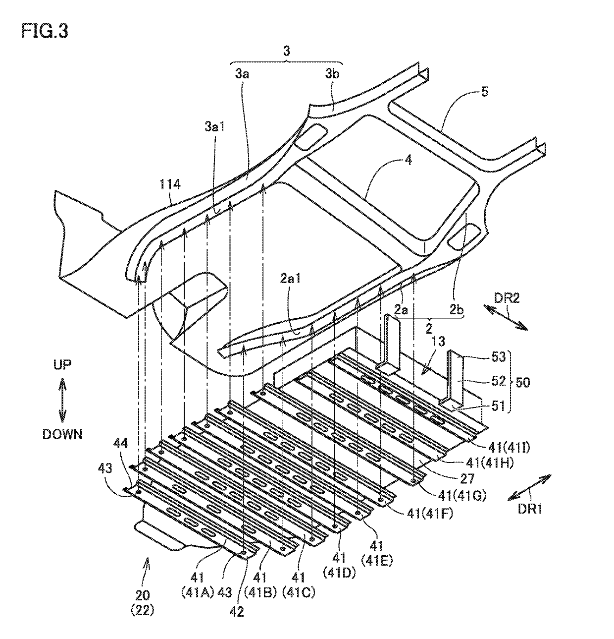
A battery pack includes: a plurality of cell stacks; a housing case configured to house the plurality of cell stacks; and a support member configured to allow a rear cross member provided in a vehicle to support the housing case, the housing case including a rear portion directed to a rear side of the vehicle in a mounted state in which the battery pack is mounted on the vehicle, the support member extending in an up-down direction and being fixed to the housing case from an outer side of the housing case so as to face the rear portion.

Description

[0001]This nonprovisional application is based on Japanese Patent Application No. 2018-054793 filed on Mar. 22, 2018 with the Japan Patent Office, the entire contents of which are hereby incorporated by reference.BACKGROUNDField[0002]The present disclosure relates to a battery pack, and particularly to a battery pack mounted on a vehicle.Description of the Background Art[0003]A battery pack configured to supply electric power to a motor is mounted on a vehicle such as an electric vehicle and a hybrid vehicle. The battery pack is assembled at a position located forward of a rear suspension, and below a floor panel of the vehicle.[0004]For example, Japanese Patent Laying-Open No. 2011-218910 discloses a vehicle having a battery pack mounted thereon.[0005]In the vehicle disclosed in Japanese Patent Laying-Open No. 2011-218910, a bracket fixed to a side member is provided with a case mount portion configured to support a battery pack case (housing case), and a suspension mount portion c...

Claims


Application Information

Patent Timeline
IPC IPC(8): H01M2/10B60L50/60B60L50/64
CPCH01M2220/20B60L50/66H01M2/1077B60L50/64H01M2/1083B60K1/04B60K2001/0405H01M50/204H01M50/249B60L3/0007
Inventor WATANABE, HIROTAKAINOUE, SHIGEYUKIINUKAI, SATOSHIMIZUNO, TERUCHIKA
Owner TOYOTA JIDOSHA KK
Learn More